Concrete Petrography: A Practical Guide
Concrete Petrography: A Practical Guide
The petrographic thin section contains a world of microscopic elements that are thinner than human hair. With a thickness that is only 30 µm, or one-third that of a human hair, it allows you to view concrete at its most basic form.
But when concrete problems crop up, petrography will become your most important resource. This branch of knowledge will enable you to determine exactly what is happening in your construction materials. With careful analysis, you can establish possible concrete problems such as finishing problems, aggregate potential, air content, problems related to water/cement ratios, or problems related to concretes that crack. Thin section analysis has become an essential resource for any core materials analysis, failure analysis, or mineral analysis. Guidelines such as ASTM C856, ASTM C295, and others provide methods for petrography analysis for both concrete aggregates and hardened concrete.
Through this handbook, you will understand the process involved in thin section making and how the quality of thin section preparations impacts your analysis. Regardless of whether your analysis is for failed concreted structures or for regular quality checks, learning concrete petrography will improve your ability to analyze materials greatly.
Understanding the Role of Thin Sections in Concrete Petrography
Thin-section analysis represents the foundation for concrete petrography, as it allows for clear vision into the microscopic world that exists for construction materials. Thin-section analysis allows for better understanding and recognition of problems from defects in materials to chemical reactions when compared to regular samples.
Why 30 µm Thickness Matters for Mineral Clarity
The thickness of standard petrographic thin sections, 30 µm, or 0.03 mm, is anything but random—if sectioned to exactly that thickness, it will become transparent to light, including that from the darkest minerals. This exact thickness allows the section to become one-third the thickness of a human hair. To say that it is extremely thin is a gross understatement, as it reveals a world that is inaccessible to the naked eye.
The critical importance of exactly this thickness cannot be emphasized strongly enough. Failure to accomplish exactly this thickness will lead to unreliable or impossible identifications. An example is the differentiation between plagioclase and K feldspar, minerals that are indistinguishable without microscopic examination, requiring exactly the optical properties that can only be discerned in exactly 30 µm thick sections. Such thickness variations can result in major errors:
- Misidentification of minerals
- Incorrect assessment of material behavior
- Missed signs of structural flaws
The thickness accuracy is, therefore, critical, and present-day processing methods can provide an accuracy to within ±1 µm for both surfaces.
Optical Properties Revealed by PPL and XPL
Petrotographic microscopes use two major methods for lighting, which highlight various characteristics of concrete ingredients:
The characteristics offered by Plane Polarized Light (PPL) include information on mineral color, pleochroic colors, and total mineral structure. Using PPL, transparent to semi-transparent particles can be made visible in thin sections.
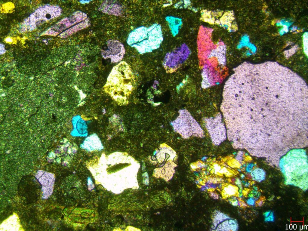
Cross Polarized Light (XPL) reveals birefringence—the splitting of light into different refractive indices—creating characteristic interference colors unique to specific minerals. Through XPL analysis, experienced petrographers can determine:
- Mineral modal content
- Overall structure
- Texture and fabric characteristics
- Presence of cracks and reaction products
Such supplementary methods enable the detection of the products of the alkali-silica reaction (ASR), void gel, gel plugs in fractured aggregate particles, and other deterioration mechanisms by virtue of their optical properties. If the fines are sufficiently fine, optical microscopy can also be complemented by SEM/EDS analysis for compositional analysis.
Metallography Consumables: Expert Tips for Better Surface Finish Results
ASTM C856 and C295 Standards for Concrete Thin Sections
The two important standards for concrete petrography analysis include ASTM standard C856 for hardened concrete samples and ASTM standard C295 for concrete aggregates.
ASTM C856 allows petrographers to:
- Identify cementitious materials, aggregate types, air distribution
- Estimate paste content, air content, and water-cement ratio
- Evaluate cracking, hydration, porosity, and deleterious reactions
Meanwhile, ASTM C295 focuses on aggregate properties that affect concrete performance, helping identify:
- Alkali-silica reactivity potential
- Alkali-carbonate reactivity potential
- Aggregate lithology
- Durability characteristics
Both standards establish important elements related to the thin section preparations, such as thickness, vacuum impregnation technique, grinding, polishing, and requirements for recording information. Therefore, by adhering to both standards, you can have confidence that the results obtained from your thin sections will pass any scientific analyses.
Ultimately, a well-prepared thin section allows you to look deep inside the concrete’s microstructure to observe details that would not otherwise be visible.
Sample Preparation and Vacuum Impregnation Techniques
Effective concrete sample preparation is the key to successful petrography. Knowing how to correctly prepare your thin sections will ensure that the true characteristics of concrete are captured without any artifacts caused by incorrect sample preparation.
Selecting Representative Concrete Core Samples
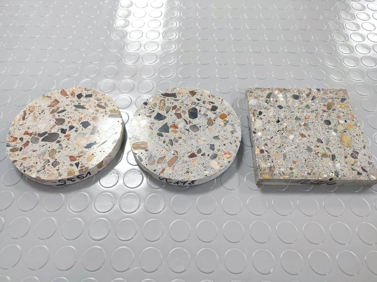
Choosing suitable specimens begins with knowing the purpose of your investigation. The specimens that clients provide for various reasons, from strength problems to deterioration analysis, include concrete specimens. Regardless of the type, concrete specimens play a critical role when it comes to analysis. The types include cores, test cylinders, samples, or deterioration samples that look like “powdery gravel”.
For petrography, it is important that the cores are of a particular size. The recommended size for a core diameter, according to ASTM C856, is at least two times, preferably three times, the maximum aggregate size. This will help ensure that a representative sample is obtained. Additionally, when assessing deterioration, it is recommended that cores are taken from regions where deterioration has occurred.
Initial Exam: Document the appearance of the specimen prior to any cutting. The examinee will look for:
- Indigenous cracks (those formed during concrete service life)
- Sampling-induced cracks (typically fresh-looking without reaction products)
- Signs of improper handling or fabrication
- Evidence of deterioration mechanisms
Remember to keep in mind that small samples can sometimes provide inadequate information. Customers must also be informed when samples can’t provide accurate information.
Vacuum Epoxy Impregnation (Fluorescent Dye) for Porous Concrete
Vacuum impregnation (VACUMET 52) is a crucial technique for processing the pores in the cementitious system. The technique helps to infiltrate the voids, cracks, and capillary pores in low-viscosity epoxy resin, thereby essentially stabilizing the fragile structures during grinding and polishing operations.
Common steps for vacuum impregnation include:
- Thoroughly cleaning and drying the specimen at approximately 60°C for 4 hours
- Placing the specimen in a vacuum chamber and subjecting it to approximately 2.7 kPa vacuum for one hour
- Introducing fluorescent epoxy while maintaining vacuum
- Releasing vacuum and optionally transferring to a pressure chamber (1-2 MPa) for deeper penetration
- Curing the impregnated specimen at 60°C for 24 hours
The addition of fluorescent dye (3% by weight) to the epoxy resin enhances visible contrast when using a fluorescent light microscope. Epoxy-filled voids, defects, and cracks are yellow, and the paste has a range of green colors depending on capillary action porosity when observed using a fluorescent light microscope. The procedure allows the visualization of structural elements that are invisible to the naked eye.
Regarding the type of epoxy, ultra-low viscosity (ULV) epoxies will better penetrate small pore structures.
Avoiding Crumble in Weak or Friable Samples
Weak or degraded concrete is particularly difficult when it comes to sample preparation. With such samples, conventional sectioning can cause considerable damage, making it difficult, sometimes impossible, to remove during subsequent processing.
To retain the integrity of fragile samples:
Initially, minimize damage caused by sectioning through the use of diamond wafer saws, such as MICRACUT 202, that are optimized for fragile samples.
Second, full vacuum impregnation using stabilizing epoxy can then follow. The substitution process in highly fragile specimens can, instead, use the solvent replacement technique by gradually substituting pore liquid with ethanol prior to adding epoxy.
The Japanese Method
Third, monitor contamination levels closely. Even minimal water (4%) or ethanol contamination can prevent proper epoxy curing. For reliable results, verify complete replacement of pore solution with ethanol using dye monitoring techniques before introducing epoxy.
Therefore, finally, it is recommended that when grinding unconsolidated materials, avoid using coarse abrasives. Rather, it is recommended that when grinding unconsolidated materials, start using finer abrasives.
If careful attention is given to these protocols for sample preparation, it is possible to successfully produce thin sections for petrography from highly friable concrete.
Cutting, Mounting, and Bonding to Glass Slides
Once the vacuum impregnation process has completed, the cutting and mounting process follows, during which your concrete sample will undergo transformation to enable it to be analyzed under a microscope. This process is also extremely important.
Using GEOFORM 102 for Precision Cutting
The GEOFORM 102 is unique, first and foremost, for its specialized, bench-top design, meant for petrographic thin section sampling only. This two-in-one machine has a cutting and grinding function, making it an essential tool for concrete petrography analysis. The machine comes equipped with a variable wheel speed that ranges from 500 to 2000 RPM, depending on the hardness samples to be processed.
The distinctive feature of the GEOFORM 102 is its capacity to cut and grind the samples to the critical thickness needed for accurate mineral analysis, which is 30 microns. The cutting compartment has a movable T-slotted top that can hold various clamping fixtures, thus making it possible to hold irregularly shaped concrete samples properly.
For optimal results, the GEOFORM 102 utilizes 200mm diameter metal-bond diamond cut-off wheels. These specialized wheels produce smoother surfaces compared to standard water-cooled saws, subsequently reducing lap time during later processing stages.
Glass Slide Roughening and Epoxy Bonding
Secondly, both the sample and the glass slide are carefully processed for bonding. To start, use 400 grit silicon carbide to roughen one side of the glass slide. This step is used to produce the microscopic roughness that significantly enhances the binding properties of the glass slide to the concrete sample.
The roughened glass slide and flat specimen surface also need to be cleaned well prior to the bonding process. If any abrasion material is left, it could weaken the strength of the bond. The petrographer can use a special machine called the ‘GEOFIX Bonding Fixture’ to evenly dispense the adhesive to the sample.
For bonding, a particular grade of epoxy(EPOCOLD) having a refractive index similar to that of quartz (about 1.5442) is used. The usual proportions for mixing are 5 parts of resin and 1 part of hardener.
Curing Time and Temperature Control for Bond Integrity
Temperature control proves critical during the curing process. Unless properly managed, excessive heat can produce bubbles between the glass and specimen, potentially ruining the sample. Ideally, maintain temperatures between 45-50°C to accelerate curing without damaging the epoxy.
The total time for its completion depends on various factors. However, with controlled heating, it will take around 2-3 hours for the epoxy to cure completely. On the other hand, without heating, it will take 40 to 48 hours, depending upon the temperature. Moreover, it also helps in avoiding bubble formation during the process.
The resinous mount then undergoes various processing, namely grinding and polishing, in achieving the desired thickness for petrographical analysis, namely 30 microns once it is fully cured.
Grinding, Polishing, and Thickness Control
To reach a thickness that is exactly 30 μm for petrographic thin sections, grinding and polishing are needed. This step is currently the most difficult process in thin section analysis, requiring accuracy for success.
Step-by-Step Grinding using Micrometer Precision
To grind concrete thin sections with GEOFORM 102, it has to start from coarse to fine grinding. Initially, remove thickness by 50 microns until it reaches 200 microns.Once it attains this thickness, it has to continue reducing by 10 microns until it attains 100 microns. Beyond that, it requires special caution without neglecting microscopic viewings.
The optimal grinding pattern will include:
- Initial grinding with 175mm diamond cup wheel (65-micron diamonds)
- Progressive steps through 400-grit silicon carbide powder
- Regular thickness verification using micrometer measurements
Targeting 30 µm Thickness: Total vs. Glass Thickness
Calculating the correct specimen thickness requires understanding the simple formula: Sample thickness = Total thickness – Glass thickness. Without this calculation, achieving the critical 30 μm dimension becomes impossible.
With a thickness of 30 μm, minerals exhibit their characteristic optical properties, for example, first-order gray interference colors in quartz observed using crossed polarized light. Quality checks become mandatory once sections reach a thickness of 100 microns, preferably every two minutes spent during grinding.
Polishing with FORCIPOL-TS/FORCIMAT-TS Systems
The FORCIPOL-TS, when used in combination with the FORCIMAT-TS, is an automated thin section preparation system that combines highly precise results. The equipment offered has a motor that is 0.75 kW, offering variable speed settings from 50 to 600 RPM, along with soft start/stop functionality.
Thin-section specimen support: The LAP–TS series, featuring stops made from boron carbide, can hold specimens from 25 μm to 35 μm thick. The corresponding support, the POL–TS, helps in the polishing process by smoothing the surface needed for microscopic analysis.
Avoiding Scratches and Air Bubbles During Polishing
Scratches commonly occur when transitioning between polishing steps or when abrasive particles contaminate finer stages. To prevent this, thoroughly clean specimens between each polishing stage. Similarly, uneven pressure or moving the polisher too quickly leads to surface scratches.
To achieve the best polish, it is recommended that there be a systematic progression from coarse to fine abrasives. This will include diamond abrasives from 18μm to 6μm, and a polishing pressure that is 15-20N for each sample, for 1-2 minutes at a time.
The appearance of air pockets, caused by improper vibrations during the concrete mix, can become rectified by using a slurry made from Cement, applied at a grit level around 400.
Microscopic Analysis and Troubleshooting Common Issues
The microscopic analysis is the end result of your preparations, wherein the thin sections demonstrate their usefulness for scientific analysis. The end result of careful preparations implemented over a period of several weeks is the valuable information derived from the microstructural analysis.
Using PPL and XPL for Mineral Identification
The polarized light microscope has two modalities for viewing that allow it to examine different properties:
- Plane Polarized Light (PPL) fixes the vibrations of the lighting in the same plane, showing color, pleochroic colors, relief, patterns of cleavage, and the presence of inclusions or zoning.
- The XPL (Cross Polarized Light) image adds a second polarizer at a right angle to the first, featuring birefringence interference colors, extinction angles, twin associations, and optical character that may be uniaxial or biaxial.
The majority of petrography is carried out by such methods, along with stereomicroscopes (light) and electron beam microscopes (electron beams).
Detecting Voids, Rim Degradation, and Uneven Thickness
Common issues frequently appearing in thin sections include:
Void formation typically results from insufficient epoxy impregnation, especially with porous materials like tuffite. Under petrographic examination, voids appear as distinct spaces that may contain secondary deposits such as alkali-silica gel.
Rim degradation manifests as thin rims of gel at cement/aggregate interfaces, indicating early-stage alkali-silica reaction. Furthermore, uneven thickness across the section creates inconsistent interference colors, making mineral identification challenging.
Improving Edge Retention and Section Clarity
To enhance edge retention, consider adding Flat Edge Filler particles to epoxy. Additionally, checking section thickness every two minutes during final grinding prevents over-grinding while maintaining uniformity.
For superior clarity, verify the uniformity of grinding using microscopic examination. Air bubbles—often developing during epoxy application or coverslip mounting—distort optical properties and should be minimized through proper vacuum impregnation techniques.
Ultimately, petrography analysis assists in understanding deterioration mechanisms, assessing the level of damage, and whether any damage will continue, making it an important component in concrete assessment.
Conclusion
The achievement of refined petrography necessitates meticulous attention to details during every step in the process of sample preparations. Clearly, the exact thickness measurement of 30 μm represents the foundation for any successful analysis, enabling the passage of light through dark minerals.
Sample selection and preparation play a crucial role in your analysis results. Therefore, adhering to standardized methods, for example, ASTM C856 and C295, will provide accurate and reproducible results. The use of vacuum impregnation fluorescent epoxy resin will improve your evaluation capabilities for the structure, cracks, or voids that could fall apart during processing.
The cutting and mounting phases demand equal precision. Specialized equipment such as the GEOFORM 102 helps achieve clean cuts while proper bonding techniques prevent bubbles and ensure specimen integrity. Subsequently, the grinding and polishing sequence gradually transforms your sample into a transparent window revealing concrete’s innermost secrets. The microscopic analysis using both plane polarized light and crossed polarized light is rewarded only after careful preparation on your part. While the two methods are quite different, both provide unique properties related to concrete, from identifications to deterioration. With that knowledge, it is possible to diagnose various problems related to finish, air content, water-cement ratio, and critical crack patterns. Concrete petrography, therefore, is an important tool in diagnosing construction materials. Although it is time-consuming and requires advanced technical knowledge, concreted petrography analysis can offer unique perspectives concerning the functionality and behavior of concrete. With microscopic analysis, important information is acquired that can help in offering crucial information for construction problems and contributing significantly to the knowledge obtained in material science.
FAQs
Q1. Why is the thickness of 30 μm important for concrete thin sections? The thickness of 30 μm is important for concrete thin sections because it helps transmit light through the darkest minerals, making them transparent. This thickness is important for distinguishing the minerals and optical properties, which are needed for petrography.
Q2. How does vacuum impregnation enhance concrete sample preparation? Vacuum impregnation is a process used to fill voids, cracks, and capillary pores in concrete samples using a low-viscosity liquid epoxy resin. This helps protect the weak concrete structure during grinding and polishing, while the additional use of fluorescent dye improves the viewable structures during microscopic analysis.
Q3. What are the major methods involved in the microscopic analysis for concrete thin sections? The major methods include the microscopic analysis using either the Plane Polarized Light (PPL) technique or the Cross Polarized Light (XPL) technique. The PPL technique analysis will provide information on the color, pleochroic properties, and general appearance, whereas XPL technique analysis will provide birefringence and special interference colors for different minerals.
Q4. How can common problems in thin-section making be prevented? To prevent problems such as scratches and vacuum bubbles, cleaning samples well between polish steps, ensuring equal pressure during polish steps, and appropriate methods for vacuum embedding can help prevent problems. If samples are fragile or soft, specialized cutting machines, along with careful methods for embedding samples with epoxy, can also prevent problems.
Q5. Which standards apply to concrete petrography analysis? The main standard for hardened concrete is given by ASTM-C856, while for concrete aggregates, it is given by ASTM-C295. These are the major standards for concrete petrography analysis. ASTM stands for American Society for Testing and Materials.


