
Metallographic Equipment: Expert Guide to Lab Setup and Selection
Metallographic Equipment: Expert Guide to Lab Setup and Selection
Regarding any materials analysis lab, the metallographic equipment is the backbone, making sure that the results of microstructural evaluations are accurate and reliable. When choosing the right equipment for your lab, you’ll need to weigh up performance against budget and look ahead to what you’ll be needing in the future. Because if you don’t have it, you won’t be able to do your analysis.
Well-known as the gold standard for microstructural analysis, properly equipped metallography labs give researchers, and quality control specialists the chance to expose the secrets of materials that would otherwise be missed.
Since the process of metallography requires a very high level of precision, it needs different techniques and equipment in each stage, from cutting and mounting to grinding, polishing and microscopic analysis. The fusion of these steps has an immediate correlation with the outcome of research and the quantity and quality of the production that follows.
Technologists now in contemporary labs must switch back-and-forth between manual and automated procedures and getting data in front of them is basically essential, which is why this guide takes a close look at all the fundamental components of metallographic equipment and what to look out for when selecting.
Precision Cutting Equipment for Sample Sectioning
Sectioning is the first major step in metallographic sample preparation. The quality of this preliminary cut directly affects subsequent preparation steps, so the quality of analysis will affect the analysis’s accuracy. Sectioning is when an equivalent sample is gathered from a parent piece in order to maintain the microstructural integrity but obtain a smooth, deformation-free surface.
Manual vs. Automatic Abrasive Cutters
In relation to sample preparation in a laboratory, manual abrasive cutters have a place in smaller labs that don’t run a high volume of tests, allowing operators to control the cutting process with precision. They are less expensive to purchase, and cost-effectiveness is a major advantage when cutting small samples or labs with a minuscule annual workload.
At the other end of the spectrum, automatic metallographic cutting machines provide a consistent and reproducible process, regardless of the operator’s level of expertise. This uniformity is really what makes them invaluable in applications that require precision. Their capability for accurate lamination composite samples and sectioning hard specimens to create smooth, square surfaces is also very unique.
The ability of pre-programmed feed systems that can control feed rates that vary according to resistance is the perfect compensation for changing material resistance in specimens from previous analyses.
| Feature | Manual Cutters | Automatic Cutters |
|---|---|---|
| Feed rate consistency | Variable (operator-dependent) | Precise (programmable) |
| Suitability for brittle materials | Poor | Excellent |
| Reproducibility | Limited | High |
| Initial investment | Lower | Higher |
| Sample quality with difficult materials | Inconsistent | Consistent |
Diamond Wafering Saw for Fine Materials
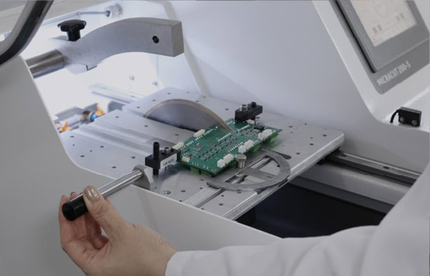
Speaking of slicing through tiny, sensitive, or very hard materials, diamond wafering saws are really up to the task. With razor-sharp, metal-bonded diamond blades that glide through the material with the utmost precision, these saws waste less material and prevent deformation, and the latest high-end precision saws take this accuracy to new heights with their sophisticated digital controls.
One of the best features of modern diamond wafer saws are touchscreens and micrometer feeds that are accurate to within 2 microns, and can cut weights of up to 1500 grams. Diamond wire saws work in much the same way as traditional saws but with a far gentler mechanism that’s well-suited for delicate crystals and substrates with thin layers.
Considerations of Cutting Speed and Feed Rate
The rate at which the cutting wheel moves through the specimen is really what determines the quality of the cut, when cutting. Coming up against a problem with brittle materials, a consistent feed rate will help to cause micro-cracks to form, and balancing out the speed of the cut and the amount of heat generated will prevent thermal damage to the sample.
Cutting efficiency is also given a boost by prolonging the life of your consumables, thanks to specially tailored cutting methods for different materials.
The contact area between the abrasive wheel and the sample is something to keep an eye on, to stop damaging the sample, and different cutting techniques such as chop cutting, pulse cutting and planar cutting can all be used to control this area. Chop cutting works well for smaller specimens, but as sample sizes grow, pulse cutting is more efficient. This adds cycles to the chop cut and grinds away at the abrasive material on the blade, sharpening it in the process and allowing the lubricant to reach the cutting area, though it does lead to faster wear. Planar cut is used for larger specimens and takes a shallow linear increment out of the sample, effectively reducing the contact area.
Petrography Explained: Essential Methods in Modern Petrology Science
Well-known brands like Microtome are offering not just the first tool, but also a total cutting package. Using the right sectioning solution cuts down preparation time and adds to the accuracy of your analysis.
System of Setting up the mounting for specimen accuracy
The mounting of the samples is next up, a process that gives the samples the shape they need to be perfectly prepared for the grinders and polishers that come later, when metallographic preparations are complete. Coming hotfooting in after this step can cause damage to the sample outlines, and will also make a huge difference in the accuracy of your analysis. Which is why the right mounting tools are so important.
Compression Mounting Presses
Hydraulic vs Pneumatic
Thermal presses are used to expose them to extremely high temperatures. 150 To 180 degrees Celsius, and crushing forces, 250 to 300 psi, or 17 to 21 bar, when hot mounting, when mounting samples for microscopy. Coming from a lab perspective, hand-operated hydraulic presses that allow you to control the heating, cooling, and pressure are being increasingly used, and because they’re so affordable, they’re ideal for small labs.
Semi-automatic presses can run pre-programmed cycles with different temperatures and pressures, requiring the operator to physically put in and take out the sample, and full automation is available in presses that have set cycles and self-cooling systems that will save you time.
A four-stage mounting cycle is what’s well-known in this process.
Heat melts the resin, compression surrounds the sample with the resin, curing sees the resin harden and, and cooling requires gentle and consistent pressure so the sample doesn’t warp, something that this method has shown to be very good at.
Vacuum and pressure systems
Castable mounting systems
In relation to mounting materials that are heat sensitive, high-pressure resistant or consist of multiple molds, cold mounting systems can be used with great success. They are essentially designed to be used in a vacuum, and are ideal for electronic assemblies, pressure-sensitive parts and materials that can be easily broken down, like porous substances, because they remove trapped air in the samples and also fill any gaps between the sample and the embedding liquid.
The vacuum impregnation process gives cold mounts a big boost in quality, and is especially good for porous materials. It gets rid of trapped air, seals any openings, smashes up cracks and shrinks down holes and also eliminates any space between the sample and the mounting medium.
Today’s vacuum systems have the ability to be programmed, come with automated vacuum control and lots of space for lots of specimens. Some of them even have vacuum cycles that alternate between vacuum and atmospheric pressure to coax out deeply trapped air.
| Resin Type | Curing Time | Shrinkage | Edge Retention | Best Applications |
|---|---|---|---|---|
| Epoxy (cold) | 8-24 hours | Lowest (0.5-1%) | Excellent | Porous samples, edge protection |
| Acrylic (cold) | 20-40 minutes | Higher (up to 7%) | Good | Quick results, standard samples |
| Phenolic (hot) | 5-7 minutes | Moderate | Good | General metallography |
| Epoxy (hot) | Varies | Low | Superior | Fine details, brittle materials |
For optimal edge retention with cold mounting systems:
- Clean specimens thoroughly to remove contaminants
- Apply release agent to molds to prevent adhesion
- Select low viscosity, low shrinkage resins
- Consider pressure curing to eliminate bubbles
As for mounting specimens, hot mounting techniques produce superior edge retention through the chemical bonding of the resin and the specimen, plus the added protection of hardness-matched fillers. Well-known to be highly effective, the outcome of the choice between mounting systems really depends on the nature of the specimen, the goals of the analysis and the need to keep the lab running efficiently.

Surface Preparation: Grinding and Polishing Machines
As preparing a sample for metallographic analysis the grinding and polishing stages are the most time consuming but they’re also the most important. Coming hotfooting through these steps will distort the sample and ruin the accuracy of the results, but this method is designed to gradually remove any distortions and give you a surface that’s representative of the sample’s true properties.
Semi-Automatic and Manual Grinder/Polishers
Laboratories must weigh the consequences of the decision, reliability and material turn-around times, when selecting between a manual and an automatic grinding/polishing system. For very small or delicate samples, manual is also the way to go, and can be utilised by experts, costing less for single sample processing, but isn’t as accurate between different operators.
Semi-automatic systems, on the other hand, have many benefits:
-
Process many samples simultaneously for higher throughput.
-
Free operators for other workloads.
-
Verify consistent sample quality.
-
Achieve flatter surfaces and better edge preservation.
-
Use less consumable materials.
For the best results in automatic systems, the operating speeds are around 300 RPM for grinding and 150 RPM for polishing. The rotation direction is very important — counter-rotation removes material faster but introduces more deformation.
Vibratory Polishers
Subsequent to existing polishing, vibratory polishers exhibit outstanding surface finishes from controlled horizontal vibrations. These purpose-built instruments work at up to 7200 cycles per minute, producing flat, deformation-free surfaces.
Modern vibratory polishers feature:
-
PZT motors for accurate vibration control (0–220 Hz).
-
Interchangeable polishing bowls (9-inch and 12-inch).
-
Leak-free two-part bowl designs.
-
New pulse modes to minimize specimen staining.

Controlled Material Removal Systems
The goal of metallographic polishing technology is to achieve controlled removal of materials. Advanced devices provide micrometer-level precision — crucial for samples such as integrated circuits.
A state-of-the-art controlled removal polisher includes:
-
Micrometer-adjustable pitch and roll controls.
-
Wheel speeds: 0–350 RPM; Head speeds: 0–150 RPM.
-
Real-time removal monitoring with 0.2 μm resolution.
-
Touchscreen interfaces for precision parameter control.
Soft materials generally require more lubricant but less abrasive, while hard materials need less lubricant but more abrasive. Best moisture management — damp rather than wet cloths — helps strip away material without removing abrasives.
Analyzing Structure with Microscope
Microscopy is the final step of metallographic preparation, where samples expose their microstructural properties. The choice of magnification and analysis software determines test quality and coverage.
Inverted vs. Upright Metallurgical Microscopes
The difference lies in optical configuration
Upright microscopes have objectives above the stage; inverted microscopes have them below.
Inverted Microscopes Advantages:
-
Handle large specimens up to 30 kg.
-
Faster sample movement and focus adjustment.
-
Less risk of damaging the specimen.
Upright Microscopes Advantages:
-
Suitable for plastics, rubber, and semiconductors.
-
Support both transmitted and reflected light observation.
Inverted models are widely used in industrial environments such as heat treatment and casting for large parts.
Macro Examination by Stereo Microscopes
Stereo microscopes offer low magnification and 3D visualization, ideal for examining fractures, welds, and surface features.
Contemporary stereo microscopes include:
-
Zoom range 0.7×–4.5× with continuous adjustment.
-
Trinocular heads for simultaneous viewing and imaging.
-
Built-in measurement functions for quantitative analysis.
Image Analysis Software
New image analysis software transforms microscopy from observation to quantification. It integrates easily with microscopes and cameras.
Key features include:
-
Automated grain size measurement
-
Phase analysis for constituent percentage determination.
-
Inclusion rating and classification systems.
-
Customizable reporting linked to Microsoft Word / Excel.
Metkon provide calibration, database management, and standardized reporting in accordance with international guidelines. Proper integration of microscopy and software enables both qualitative and quantitative evaluation for quality control, failure analysis, and research applications.
Hardness Testing Instruments for Material Characterization
Hardness testing quantifies material resistance to deformation and is key for performance evaluation, quality control, and wear prediction.
Microhardness Testers: Vickers & Knoop
These methods use diamond indenters to measure localized hardness.
-
Vickers: square-based pyramid indenter; both diagonals measured.
-
Knoop: elongated rhombohedral indenter (~7× longer); penetrates half the depth of Vickers. Ideal for thin layers (e.g., aluminum foil) and brittle materials like ceramics and glass.
Optimal magnification ensures ≤2% edge resolution of diagonal length.
High-Volume Hardness Testing: Rockwell and Brinell
-
Rockwell: applies a preliminary 10 kgf load, then 60–150 kgf. Direct hardness readings make it ideal for high-throughput production.
-
Brinell: uses large indenters for coarse-grained materials (cast iron, aluminum alloys). Indentation diameter gives average hardness over non-uniform structures.
Dual-function testers using both methods are highly efficient for varied materials.
Automatic Load Application and Data Management
Modern hardness testers are automated, performing up to 150 indentations/hour with 10 s dwell times.
Automation software such as Metkon offers:
-
Data mining for specimen and edge detection.
-
Case-depth and statistical analysis.
-
Weld and geometric measurement functions.
-
Standard file export (CSV, XLS, etc.).
-
Programmable parameters (force, dwell time, pattern).
-
Motorized XY stages for unattended multi-sample testing.
Looking at to cut, mount, and polish metallographic samples, getting the equipment right is crucial to the accuracy of the diagnostic results and the efficiency of the lab. The first step is precision cutting, which is followed by mounting systems that lock the samples in place and standardize the analysis. The grinding and polishing of the surface, and the use of a microscope are next and bring out the intricate details, hardness testing gives us numbers to go along with what we see.
Manual systems can be very affordable for tiny labs, but automated systems mean that larger labs can churn out lots of results consistently. Coming hotfooting into the picture, the type of material, the size of the sample and how precise the analysis needs to be all play a role in picking the right equipment.
Well-known as long as the equipment is chosen, serviced and put together well, laboratories can depend on being able to see the properties of materials, streamline their production, and do accurate failure analysis, transforming tiny details into clear, understandable results.


