Stainless Steel: A Practical Guide to Metallographic Preparation
Stainless Steel: A Practical Guide to Metallographic Preparation
The narrative of stainless steel stretches beyond the glossy rust‑proof sheen most people instantly picture. Tucked beneath that shell lies a labyrinthine micro‑architecture—a mosaic of phases and grain boundaries—that dictates its strength, durability and how it performs across a staggering array of applications. Though it underpins everything from kitchen utensils, to sophisticated aerospace components its true character stays hidden from the naked eye.
Grasping those hidden traits calls for metallographic preparation—a careful step‑by‑step routine that brings the microscopic makeup of stainless‑steel samples into view. This approach lays key details like grain boundaries, phases and any lurking defects that ultimately dictate how the material behaves in real‑world conditions. Being proficient in prep is also a cornerstone, for quality control, failure analysis and the development of new materials.
This all‑purpose handbook first surveys the stainless‑steel grades then explains why metallographic analysis matters hands you a clear step‑by‑step preparation routine points out the usual snags you might encounter and finally shows you how to decode what you see under the microscope.
Delving into the Diverse World of Stainless Steel Types
Classifying steel goes far beyond a simple measure of corrosion resistance. Each alloy bears its microstructural fingerprint, which shapes its mechanical behavior and points to the applications where it performs best. By probing these varieties essential insights emerge for metallographic preparation and analysis.
Ferritic: low‑carbon, magnetic and easily cold‑worked.
Ferritic stainless steels carry a chromium content—roughly 10.5 % to 30 %—which grants them excellent resistance, to oxidizing environments. Their body‑centered cubic crystal structure makes them inherently magnetic, a characteristic that distinguishes them from other stainless varieties. Because the carbon level is typically kept below 0.10 % these grades cannot be hardened through heat treatment; instead they are strengthened by working.
In addition ferritic stainless steels contain no nickel, which keeps them inexpensive and less prone to stress corrosion cracking. Commonly dubbed the “400 series ” these alloys are used widely in exhaust systems, kitchen appliances and a range of architectural applications.
Martensitic: can be. Offers high strength.
At a glance martensitic stainless steel is a chromium‑carbon alloy that settles into a body‑centered body‑centered tetragonal crystal arrangement. Typically its chromium content hovers between about 11.5 % and 18 % while carbon may be present at levels high as roughly 1.2 %. In contrast to ferritic grades martensitic varieties are notably receptive, to heat‑treatment allowing their characteristics to be fine‑tuned through thermal processing.
When given a heat‑treatment cycle these ferromagnetic alloys can climb to a tensile yield strength of roughly 1900 MPa (275 ksi) far outpacing the about 275 MPa they show in the annealed state. As a result they are employed in steam turbines, surgical instruments, cutlery, valves and ball bearings—applications where moderate corrosion resistance coupled with strength is essential.
Austenitic: an alloy that’s amenable, to cold‑working.
Austenitic stainless steels typically contain about 14 %–28 % chromium and 2 %–35 % nickel, a blend that yields a microstructure that essentially refuses magnetic attraction. In fact they are the stainless‑steel family that is fully paramagnetic with a magnetic permeability barely above unity—roughly 1.01, to 1.02.
These non‑heat‑treatable alloys develop their properties through working. A recent study found that sprinkling 0.02 wt % of TiC‑TiB₂ nanoparticles into the matrix sharpens the microstructure pulling grain size down from roughly 23.7 µm to about 18.4 µm while at the same time boosting hardness, yield strength and impact toughness. Consequently austenitic grades emerge as suitable for cryogenic applications, where both formability and corrosion resistance, at sub‑zero temperatures are critical.
Duplex: a blend of ferrite and austenite
Living up to its label duplex stainless steel comprises a microstructure where austenite and ferrite coexist in a near‑equal 1:1 ratio; this marriage of phases imparts a robustness and corrosion‑defence that generally eclipse those of austenitic variants such, as 316.
Interestingly duplex grades rely on alloying elements, than fully austenitic stainless steels, which cuts costs appreciably while still delivering top‑level performance. In addition their unique microstructure develops a eye‑catching pattern when the specimen is properly prepared and etched so they’re relatively easy to spot during metallographic inspection.
Alloy grades strengthened through precipitation hardening
First rolled out in 1946 precipitation‑hardening (PH) stainless steels answered the call, for alloys that could hold up under temperatures while staying both strong and corrosion‑resistant. With the heat‑treatment they can reach tensile strengths of 850–1,700 MPa and yield strengths of 520–1,500 MPa—about three to four times the strength of the common 304 or 316 austenitic stainless steels.
The PH family can be broken down into three groups: low‑carbon martensitic (such as 17/4PH) semi‑austenitic and fully austenitic. Their exceptional strength comes from alloying copper, molybdenum, aluminum and titanium which during aging form a fine mesh of precipitates, along planes. These tiny particles lock the surrounding matrix into a strained state dramatically raising the material’s mechanical performance.
A Step‑by‑Step Approach, to Metallographic Preparation
A well‑executed metallographic preparation pulls hidden features into view turning them into evidence that can be examined and recorded. The care invested in that preparation directly dictates how accurate the downstream analysis will be and consequently shapes the conclusions, about stainless‑steel properties.
Cutting: sidestep heat buildup. Stave off deformation.
Proper sectioning starts with cutting directing a generous stream of coolant straight into the cut. This not yields a smoother surface than a dry cut would but also keeps the heat low enough to preserve the metal’s microstructure. For steel blade selection is essential—softer grades pair best with harder‑bond blades that enjoy a longer service life while harder grades require softer‑bond blades that wear away constantly exposing fresh abrasive.
When precision is essential wafering blades have the edge, over wheels. These cutters work with loads and stay cooler cutting down on damage when you’re slicing right up against the features you care about. Whatever method you choose keeping cooling steady is a must; otherwise a work‑hardened layer will. You’ll need a lot of grinding to get rid of it.
Mounting: hot, versus cold approaches
Mounting yields specimens of geometry that safeguard their edges and streamline handling in later preparation steps. In hot‑compression mounting, thermosetting or thermoplastic resins are applied under temperatures (≈150–200 , °C) and substantial pressure (≈100–300 bar).
On the side cold mounting employs liquid resins that polymerise on their own without any external heat or pressure—a boon for specimens that are sensitive, to temperature. Acrylic‑based systems set in a hurry under thirty minutes whereas epoxy‑based systems though slower to cure provide stronger adhesion, less shrinkage and noticeably better edge retention. When working with compression mounts allowing them to cool gradually while under pressure dramatically cuts down on the formation of shrinkage gaps.
Grinding: the ritual that clears away surface damage
Grinding sets up a reference surface while gradually stripping away any cutting damage. Start with a silicon‑carbide paper (120–180 grit) and then work through finer grits—240, 320, 400 and finally 600. Each successive step wipes out the scratches left by the grit leaving only finer subtler marks.
Throughout the grinding operation keep a force—roughly 25–30 N—and spin the disc at about 250–300 RPM. Water works best as a coolant and lubricant swiftly sweeping, away chips while keeping the temperature from spiking. After each grinding pass give the specimens a rinse to ward off cross‑contamination that could otherwise invalidate your preparation.
Polishing: yielding a surface thats utterly free of any scratches.
Polishing chips away the uneven bits moving through the workpiece in stages. In the stage diamond suspensions—usually 9 µm, 6 µm and 3 µm—are applied to a medium‑hard pad scrubbing away the fine scratches left by grinding. The final pass, using a colloidal silica slurry ( 0.05 µm) or an alumina blend (ranging from 0.3 to 0.05 µm) on a soft‑nap cloth gives the sample a mirror‑like finish thats essential for microscopic examination.
Achieving the balance in polishing parameters is crucial. For substrates a generous amount of lubricant is required while the abrasive load is kept low;, for harder substrates the opposite holds—minimal lubricant paired with a more aggressive abrasive because they tend to wear away faster. The polishing pad should be merely damp than soaked since excess fluid will wash the abrasive away and diminish material removal.
Etching: peeling back layers to reveal the underlying microstructure
After polishing the etchant nibbles at the surface in a way exposing the underlying microstructural details. Since stainless steels are naturally resistant to corrosion choosing the etchant becomes a pivotal decision. Austenitic 300‑series alloys, loaded with amounts of chromium and nickel tend to shrug off the etchant more stubbornly, than the martensitic 400‑series grades.
Because stainless steels rapidly form a protective oxide layer swabbing is usually favored over immersion. When the alloy proves electrolytic etching often yields a more even result. In duplex alloys a dedicated etchant—Murakami’s reagent for example—highlights the sigma phase, with clarity.
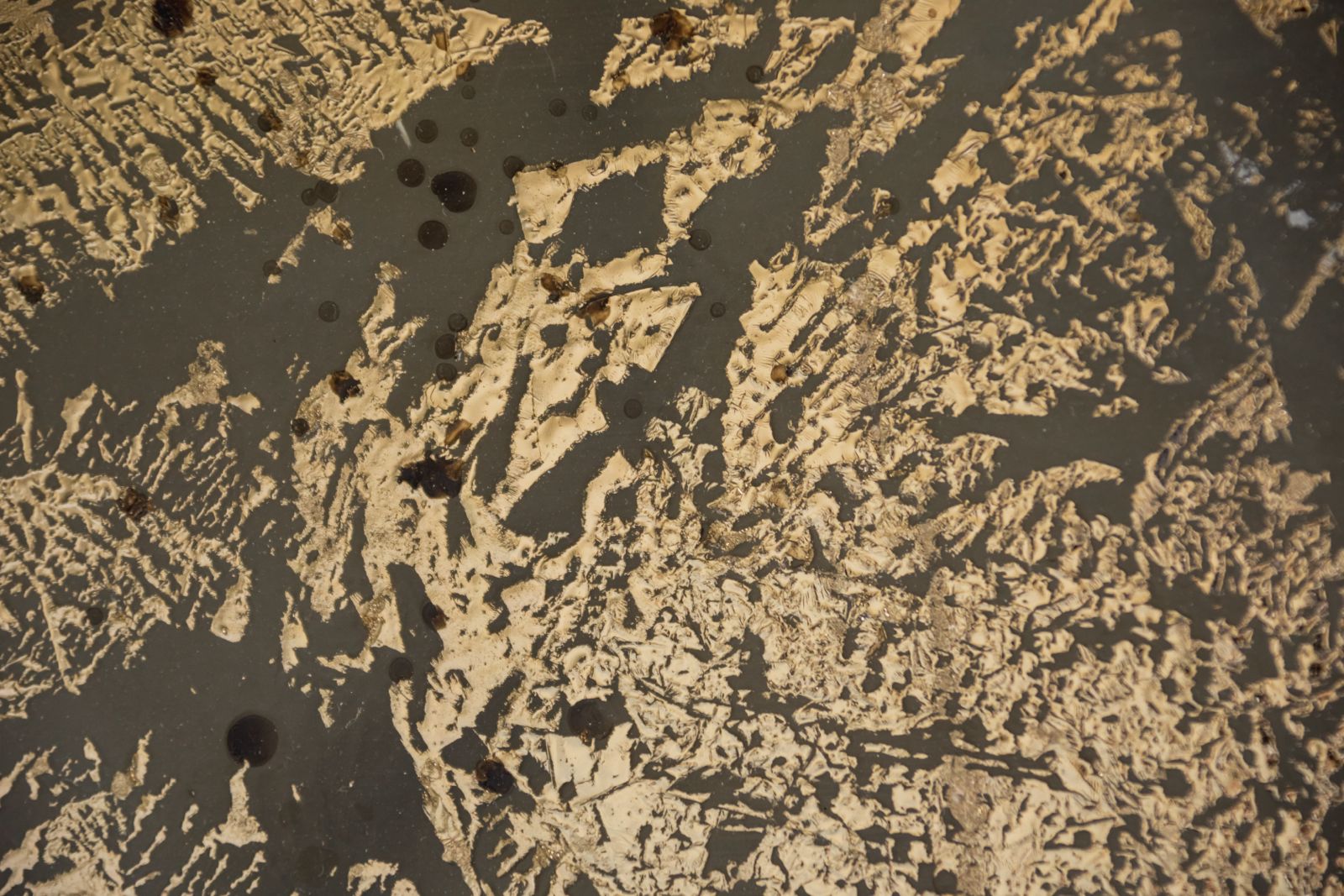
Explanation of Stainless Steel Microstructures
Grasping the interpretation of microstructures within stainless steels gains us important knowledge about material performance and the history of processing. Prepared correctly, specimens disclose an intricate terrain that trained eyes can read to make predictions about mechanical properties and corrosion characteristics.
Identification of ferrite and austenite
The three main phases within the steel all contain different crystal structures that define the properties. Ferrite contains the body-centered cubic structure with an atom at each corner and also one in the center. Depending on the temperature the formation occurred at, it is either called delta ferrite at the higher temperature or alpha ferrite at the lower temperature. Austenite has the FCC structure with the atoms at each corner and also one on each face, creating an overall more densely packed structure. Martensite is formed by the rapid cooling of the austenite and has an irregular body-centered tetragonal (BCT) structure with the development of extremely exceptional strength and hardness.
Identification of twins, carbides, and inclusions
Twin boundaries within austenitic stainless steels arise due to the 60° rotation about a crystallographic direction and produce high-angle boundaries that hinder crack growth and enhance corrosion resistance. Such low-energy boundaries can only be observed with proper preparation. Carbides mainly M23C6 and M7C3 usually precipitate along the grain boundaries during exposure to heat and can leach the surrounding region’s chromium. While inspecting welds, delta ferrite islands can be an indication of the right ferrite percentage (12-15%) to inhibit solidification cracking.
Detecting intergranular corrosion signs
Intergranular corrosion preferentially attacks the grain boundaries and is usually caused by sensitization due to welding or heat treating between 900-1400°F (482-760°C). This process consumes nearby areas’ chromium to form chromium carbides (Cr23C6) by weakening the protective passive coating. For detection purposes, electrolytic etching with 10% oxalic acid will either reveal step structure (resistant material) or ditched structure (sensitized material) on the grain boundaries. Grain-boundary engineering can be used to reduce this problem by producing large twin-related domains to impede corrosion propagation.
Phase contrast by way of color etching
Color etching provides improved phase differentiation over conventional methods. Beraha’s reagents specifically color ferrite in steels with double phases, and aqueous 20% sodium hydroxide gives reliable ferrite coloring. For the identification of the brittle intermetallic compound sigma phase that significantly lowers toughness, Murakami’s reagent remains particularly useful. For the identification of martensite in duplex stainless steels, the best Beraha color etching specifically brings to view martensite and differentiates it from similarly-etching ferrite.
Stainless steel shows its true character by virtue of competent metallographic preparation. We learned about the intricately complex microstructures that characterize the performance of different grades of stainless steel—ranging from ferritic and martensitic through austenitic to duplex and precipitation-hardening grades. They all have distinguishing characteristics that dictate the kind of application each is best suited for.
Accurate metallographic preparation undoubtedly provides the basis for quality control, failure analysis, and materials development. Without this most important procedure, the inside characteristics that control strength, corrosion resistance, and durability would be impossible to see. The meticulous progression of cutting and sectioning, mounting and grinding and polishing and etching converts dull metal specimens to descriptive microstructural maps that relate the entire history of the material’s processing.
There will always be challenges to confront during the preparation. Distortion during grinding, pull-out of carbides within martensitic steels, uneven etching, and challenges in revealing delta ferrite or the sigma phase demand special remedies. Knowing these challenges in advance enables the metallographer to modify techniques and obtain the best outcome. Accurate interpretation of what is seen through the microscope is perhaps the greatest asset within metallographic analysis. Determination of ferrite, austenite, martensite, twins, carbides, and inclusions is exceedingly vital to material performance understanding. Of equal significance is the differentiation between signs of intergranular corrosion or the use of color etching to gain phase contrast.
The hidden secrets of stainless steel become accessible through this methodical approach. What once appeared simply as a shiny, corrosion-resistant material transforms into a complex metallurgical system with predictable behavior based on its microstructure. This understanding ultimately leads to better material selection, improved manufacturing processes, and more reliable performance across countless applications. Metallographic preparation mastered thus yields much more than visually appealing micrographs—it yields critical information that fuels technological breakthroughs from the aerospace and automotive industries to medical device manufacture and power generation. Stainless steel’s microscopic realm, once appropriately uncovered, is the key to unlocking many an engineer’s hardest problem today.


