Weld Inspection Techniques: Expert Guide to Sample Preparation
Weld Inspection Techniques: Expert Guide to Sample Preparation
Weld inspection techniques are the backbone of structural reliability in industries where precision and accuracy cannot be derailed. Aerospace, infrastructure, and energy industries demand flawless welds – any defect can result in catastrophic outcomes and gigantic operating losses. Metkon provides specialized sample preparation solutions that ensure accurate weld quality determination via reliable metallographic analysis.
Weld inspection methods are classified into two broad categories: non-destructive and destructive testing methods. Both methods satisfy a range of quality control requirements. Visual inspection is applied for initial surface-level inspection, while advanced methods like ultrasonic and radiographic testing yield essential inside flaws.
Automated Sample Preparation | Cut Impact, Save Time & Costs
This guide revolves around sample preparation – the foundation of good weld testing. Careful cross-sectioning, grinding, polishing, and etching procedures have a direct effect on your ability to identify possible failures. Our equipment and methods are variable to varying material alloy content and weld shape to offer uniform results in various applications.
Principal Sample Preparation Benefits:
- Acurate Analysis: Reveals microstructural information that is not visible to surface inspection
- Reproducible Results: Uniform techniques ensure surefire quality testing
- Thorough Assessment: Both external and internal weld characteristics
We explain why proper preparation procedures vary with material properties and welding operations, constituting the technical foundation for proper weld quality examination.
Summary of Weld Inspection Categories
Weld testing methods classify into two groups based on their impact on the test piece. Understanding these categories makes proper method selection possible based on application, material, and quality requirement.
Destructive vs Non-Destructive Testing (NDT)
Destructive testing intentionally deteriorates samples to reveal internal characteristics otherwise hidden from view. Such processes alter specimens fundamentally but provide complete microstructural information essential to weld qualification and failure analysis.
Destructive testing protocols include cross-sectioning to analyze the microstructure, bend testing to establish ductility, tensile testing to establish strength, and macro-etching to reveal the fusion zones. Our high-precision cutting equipment like MICRACUT series and mounting systems ensure adequate sample preparation for destructive testing.
Metallography Consumables: Expert Tips for Better Surface Finish Results
Non-destructive testing evaluates welds without compromising the structural integrity. It is very important in production parts and in-service components. The NDT methods locate the surface and subsurface defects with the functional status of the component maintained. Some of the basic techniques include ultrasonic testing, radiography, magnetic particle testing, and dye penetrant testing.
Visual Inspection as Primary Assessment
Visual inspection is the initial test step in every weld inspection process. The method easily identifies surface imperfections like undercuts, spatter, incomplete fusion, and surface porosity.
Successful visual inspection is attained through proper surface preparation. Clean slag- and spatter-free surfaces and contaminant-free surfaces enable precise weld quality examination. Appropriate lighting conditions (min. 1000 lux) and proper positions for examination are necessary for careful evaluation.
Visual inspection can identify surface flaws but won’t identify concealed defects. This limitation makes visual testing an effective screening test to determine whether additional testing must be done.
Method Selection Guidelines
Inspection method selection is dependent on application criticality, material type, accessibility, and regulation.
Destructive testing is of the most utility for procedure qualification, welder certification, and failure analysis. These applications justify destructive testing of test specimens in order to obtain precise performance and microstructural data.
Production inspection and in-service items need NDT techniques. The NDT method chosen is a function of defect type and material chemistry. Magnetic particle testing is well suited for surface cracks in ferromagnetic materials. Ultrasonic testing is best at detecting internal voids in heavy sections.
Visual inspection should precede all other methods regardless of application. Use of more sophisticated testing is generally negated by failed visual inspection, saving time and cost. Many codes and standards require successful visual inspection before proceeding with other NDT methods.
The Ultimate Guide to Grinding and Polishing: Techniques, Equipment, Materials, and Best Practices
The heat-affected zone receives special attention when being inspected. This area will typically exhibit altered microstructure and potentially reduced strength compared to base material and fusion zones.
Visual and Surface-Level Inspection Methods
Surface preparation is accountable for the accuracy of weld inspection to ensure that it is achievable to identify large defects that impact structural strength. Accurate sectioning, grinding, and polishing techniques reveal the actual extent of weld quality using systematic methodology.
Weld Visual Inspection Criteria Assessment
Visual inspection is the first assessment step in weld inspection processes. Welds are examined under optimal lighting conditions (at least 1000 lux) using proper magnification where required. Key visual criteria are:
- Conformity of weld profile to design requirements
- Proper weld dimensions and length
- Detection and identification of surface discontinuities
- Uniform appearance along the weld zone
Standardized testing procedures need precise documentation via photographs and methodical recording. Visual inspection defines the requirement for further testing techniques as per surface observations.
What is the Vickers Hardness Test? | Method, Applications & Advantages
Surface Preparation Process for Reliable Results
Successful visual testing necessitates methodical surface preparation with specialized equipment and well-established techniques:
Precision Sectioning: Our MICRACUT and SERVOCUT series enables precise cutting conditions:
- Feed rates: 100-400 μ/sec for precise sectioning
- Rotational speeds: 2000-2800 RPM for precise cuts
- Cooling systems to prevent heat damage during sectioning
Hot Mounting Process: ECOPRESS mounting systems ensure stability to the specimen:
- Temperature control: 180-190°C for optimal resin flow
- Pressure application: 220-260 bar for even mounting pressure
- Cooling cycle: Standard reduction to 35°C for handling
Progressive Grinding: Step-wise abrasive progression yields high-quality surface finish
- Treatment grits: 180-320 for initial material removal
- Applied forces: 20-25N per sample for reproducible results
- Process speeds: 100-250 RPM with water cooling
- Sequential progression through 600, 800, to 1200 grit
Diamond Polishing: Final surface preparation utilizes precise parameters:
- Diamond suspension: 3μ followed by 1μ particle size
- Applied forces: 15-20N for controlled polishing
- Disk speeds: 150 RPM with specialized lubricants
- Processing time: 1-3 minutes per polishing step
Metallographic Etching: 10%-3% Nital solution reveals weld areas and microstructural details required for effective assessment.
Surface Defect Identification and Classification
Successful surface preparation reveals typical weld defects that degrade structural performance:
Undercuts are grooves in weld edges where base metal melted with inadequate filler addition. Undercuts reduce effective thickness and create stress concentration areas.
Spatter occurs as ejected metal particles deposited on surrounding surfaces. Excessive spatter indicates parameter differences that are a sign of bigger problems of quality.
Incomplete Fusion appears as poor fusion between weld metal and base material. This critical defect significantly compromises joint strength and appears as linear lines along weld interfaces.
Other flaws include porosity, cracking, inclusions of slag, and reinforcement irregularities. Once the defects are detected, microscopic examination with metallurgical systems at 50x to 500x magnifications provides detailed microstructure analysis and determination of defect extent.
Non-Destructive Testing (NDT) Methods for Welds
Non-destructive testing facilitates thorough weld inspection without structural compromise. The methods preserve component functionality while providing critical defect information essential for quality control purposes.
Ultrasonic Weld Inspection for Internal Flaws
Ultrasonic inspection detects internal discontinuities beyond the capability of surface inspection methods. High-frequency sound waves introduced via weld material provide accurate analysis through interpretation of reflected signals.
Ultrasonic inspection benefits include:
- Superb planar defect detection including cracks and lack of fusion
- Up to several inches section penetration
- Accurate flaw location and sizing measurement
- Digital result storage for documentation and comparison
Sophisticated ultrasonic machines have automated and manual operating modes. Automated machines achieve high-precision hardness profiling along weld areas and identify weak areas of concern. Characteristics of sound waves vary according to defects, enabling operators to recognize acceptable anomalies and critical imperfections that require rectification.
Radiographic Weld Inspection (X-ray Testing)
Radiographic inspection provides detailed internal weld visualization with the use of penetrating radiation. Radiographic inspection generates permanent visual records of internal conditions of welds for quality documentation.
Major radiographic characteristics:
- Volumetric defect visibility like porosity and inclusions continuously
- Extensive internal weld quality reporting
- Multi-angle inspection of complex geometries
- Verification of penetration of joints
The process of radiography positions the radiation source on one side of a weld with a detector on the other side. Thick materials are highlighted as dark areas on the final image. Trained analysts review these images to identify and categorize defects according to applicable standards.
Magnetic Particle Inspection (MPI) for Surface Cracks
MPI detects near-surface and surface flaws in ferromagnetic material using magnetic fields and iron particles. This method effectively reveals defects through particle collection patterns.
Standard MPI process:
- Magnetization of the weld area
- Painting with magnetic particles (dry powder or wet suspension)
- Checking for particle collection indicating defects
Magnetic particle inspection detects minute surface cracks that cannot be detected visually. Magnetic particle inspection effectively detects heat-affected zone defects that degrade weld strength. Magnetic particle inspection continues to be limited to ferromagnetic materials and detects only surface or near-surface defects.
Dye Penetrant Testing (PT) for Open Surface Defects
Dye penetrant testing is a low-cost method of detecting surface-breaking flaws in nearly any material that is not porous. Colored or fluorescent dye penetrates surface openings to reveal defects.
PT procedure sequence:
- Thorough weld surface cleaning
- Penetrant dye application
- Controlled penetration dwell time
- Excess penetrant removal
- Developer application to draw out penetrant from defects
- Inspection under appropriate lighting conditions
PT effectively identifies undercuts, porosity, and surface-breaking cracks. The method works across various non-porous materials, providing versatility for different metallurgical applications. PT detection remains limited to surface-breaking defects and requires careful surface preparation.
Each NDT technique serves to meet certain inspection needs. Effective weld inspection programs frequently involve a combination of methods depending on application criticality, material type, and anticipated defect modes. Familiarity with the capabilities and limitations of each method ensures correct selection for individual weld inspection applications.
Sample Preparation for Metallographic Weld Analysis
Metallography testing reveals weld quality on the microscopic level. Adequate sample preparation techniques uncover vital information on fusion zones, heat-affected zones, and potential defects invisible to routine inspection methods.
Weld Cross-Section Preparation Techniques
Cross-sectioning properly requires precise cutting operations to prevent causing artifacts. Equipment selection relies on material hardness and specimen size. Our MICRACUT series provides accuracy cuts for thorough examination, whereas SERVOCUT series treats larger specimens with ease.
Cutting parameters under optimal conditions are:
- Feed rates: 100-400 μ/sec
- Rotational speeds: 2000-2800 RPM
- Travel distances: 30-150 mm depending on sample size
Cut across the weld seam to expose all zones – base material, heat-affected zone, and fusion zone. Adequate cooling with soluble oils like Metcool prevents thermal damage which alters microstructure.
Grinding and Polishing Parameters for Weld Zones
Gradual grinding and polishing procedures reveal true microstructure features. Our machines deliver reproducible results for different weld types.
Grinding sequence
- Coarse abrasives: 180-320 grit SiC or 54μ diamond
- Medium abrasives: 600-800 grit or 18μ diamond
- Fine abrasives: 1200 grit or 6μ diamond
- Application force: 20-25N per sample
- Disk speed: 200-250 RPM with water lubrication
Polishing parameters:
- Initial polish: 3μ diamond suspension on appropriate cloth
- Reveal polish: 1μ diamond suspension
- Times reduced force: 15-20N at 150 RPM
- Processing time: 1-3 minutes per step
Mounting Techniques for Structural Integrity
Mounting supports samples during preparation without harming edge integrity. Two mounting methods serve different application purposes.
Hot mounting specifications:
- Equipment: ECOPRESS mounting press
- 180-190°C
- 220-260 bar
- 3 minutes
- Standard cooling to 35°C
Cold mounting applications:
- Prevents thermal exposure that may alter properties
- Maintains sample integrity for temperature-sensitive materials
Properly prepared samples are investigated microscopically at magnifications of 50x to 500x, and microstructural features that affect weld performance and reliability are observed.
Etching Procedures for Revealing Microstructure
Etching distinguishes macro-microstructural features in welds. 10%-3% Nital solution easily reveals steel weld features by selective attack at grain boundaries.
Etching process:
1.Brief etchant immersion (seconds)
2.Water rinsing at a fast rate
3.Long drying to prevent staining
The method easily reveals heat-affected zones and fusion boundaries under microscopic examination.
Advanced Evaluation and Defect Characterization
Microscopic analysis provides the ultimate verdict of weld quality, revealing key defects still not picked up by conventional inspection methods. Our metallographic testing tools and analytical techniques enable precise characterization of defects and their influence on structural behavior.
Microstructure Analysis of Welds under Microscope
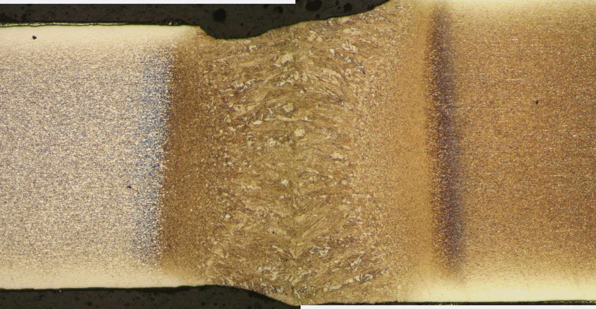
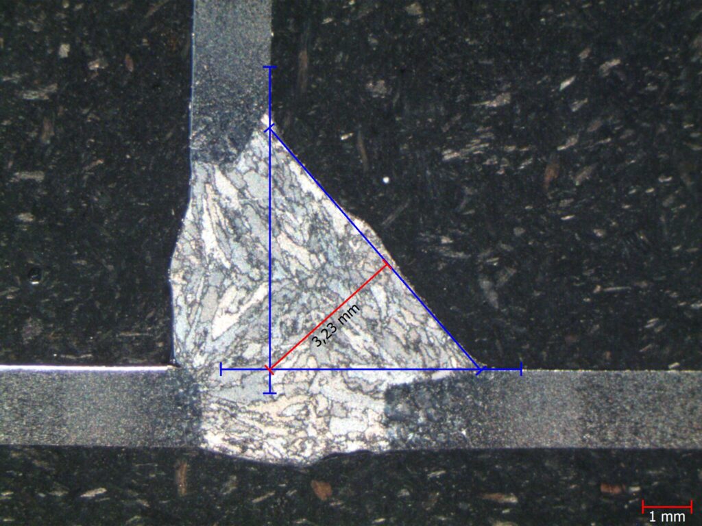
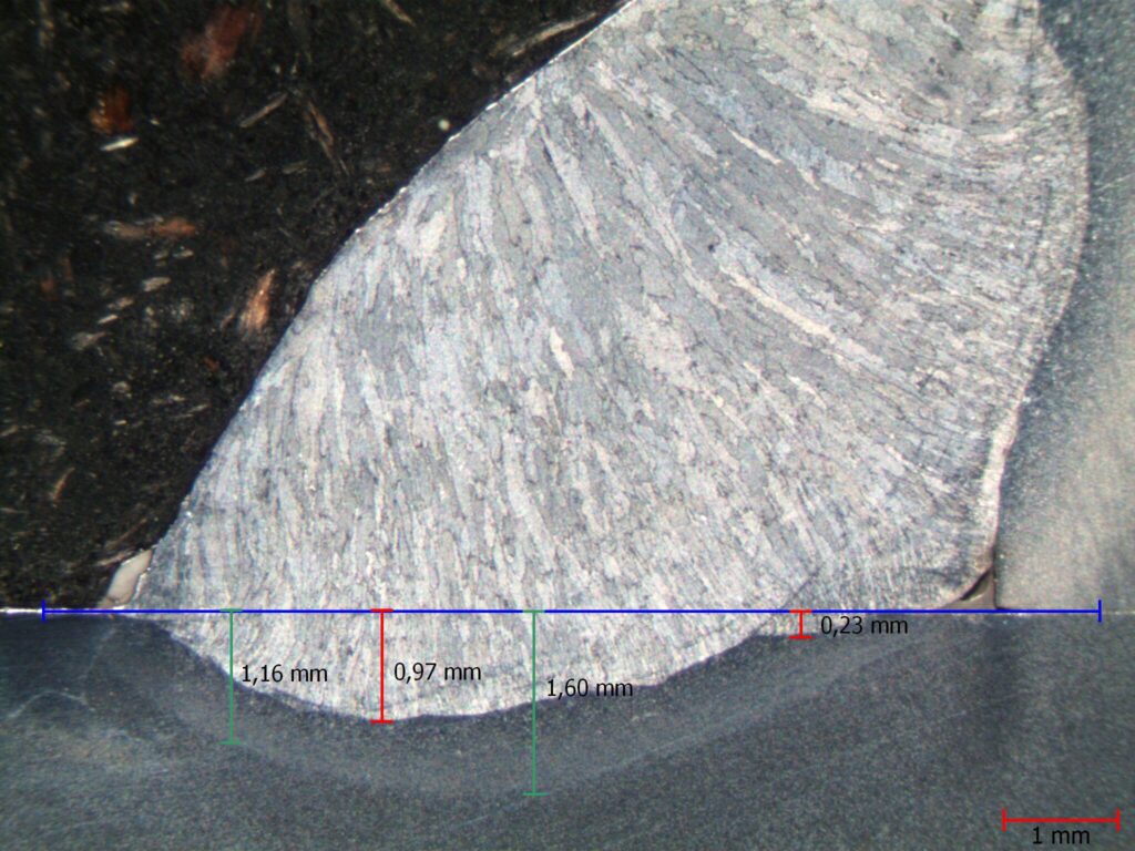
Proper etching using 3% Nital solution shows distinct weld zones during metallurgical testing. Our Metallurgical Microscope provides distinct differentiation of fusion zone, heat-affected zone (HAZ), and base material at 50x to 500x magnifications. Grain structure changes and microstructural changes revealed in the tests have direct effects on weld performance properties.
Systematic inspection at successive magnifications detects grain boundary conditions, phase transformation, and structural discontinuities in all weld areas. This detailed analysis correlates microstructural characteristics with mechanical properties and service behavior.
Weld Porosity Detection and Classification
Gas-formed voids appear as rounded dark features distributed throughout the weld cross-section. Accurate classification includes measurement of pore size, frequency, and distribution patterns. Isolated porosity typically has low risk, while cluster or aligned porosity significantly reduces joint strength and fatigue life.
Our techniques of analysis provide precise measurements of void features for proper evaluation of porosity influence on weld acceptability according to applicable standards.
Crack Detection in Welds Using Image Analysis
The MESURA 200 image analysis system provides improved crack detection through high-resolution digital processing. The technology measures microscopic cracks that are often missed with traditional visual examination. Precise determination of crack size, orientation, and location provides essential information for joint serviceability evaluation and residual life prediction.
Digital analysis enables precise characterization of the crack independent of the inspector and inspection environment, with consistent quality evaluation.
Hardness Testing of Welds Through HAZ and Fusion Zone
Hardness measurements across weld sections reveal mechanical property variations affecting performance under load conditions. Our hardness testers provide accurate profiles from base material through the heat-affected zone to the fusion zone. These measurements identify potential weak spots or hardening areas that will lead to service failure.
Hardness profiles ensure success of welding conditions and verify correct results of heat treatment, ensuring welds meet specified performance requirements.
Conclusion
Weld inspection techniques provide the underlying platform for structural integrity in important industries. Proper sample preparation has a direct influence on the reliability and accuracy of weld quality assessment. Non-destructive and destructive testing techniques are both provided with flexibility according to specific application requirements.
Surface preparation – sectioning, mounting, grinding, polishing, and etching – reveals critical information inaccessible to visual inspection. Reproducible parameters provide reproducible results for differing types of welds and materials. Technicians can identify defects like undercuts, spatter, and incomplete fusion before they impair the integrity of the structure.
Our microscopy facilities provide precise microstructural analysis with magnifications ranging from 50x to 500x. Hardness testing across weld zones validates welding conditions and identifies potential failure locations. Microscopic porosity and cracks are identified by sophisticated image analysis systems that cannot be identified by the standard methods.
Combining appropriate sample preparation equipment with formal inspection procedures enables weld quality assessment with high accuracy. These techniques eliminate costly failures and ensure safety for structures that depend on high-quality welded joints.
Metkon’s state-of-the-art cutting equipment, mounting equipment, grinding and polishing equipment, and microscopy enables laboratories to deliver the precision required for the correct assessment of welds. Our solutions complement the high-level requirements of quality in aerospace, infrastructure, and energy application where weld integrity is not a choice.
FAQs
Q1. What are the main weld inspection techniques? There are basically two types of weld inspection techniques: destructive and non-destructive testing. Sacrificing the specimen is needed in destructive testing to reveal internal characteristics, while non-destructive testing examines welds without damaging the component.
Q2. Why is visual inspection important in weld testing? Visual inspection is the critical initial step in weld testing. Visual inspection detects surface flaws and determines whether further sophisticated testing is required. Surface preparation and suitable lighting conditions are the requirements for effective visual inspection.
Q3. What are some common surface weld defects? Common surface weld defects include undercuts (edges of grooves on the weld), spatter (metallic particles attaching to adjacent surfaces), and incomplete fusion (not fusing weld metal and base material). These defects have significant effects on weld quality and strength.
Q4. What are the non-destructive tests utilized for weld inspection? Common non-destructive tests used for weld inspection are ultrasonic testing for internal flaws, radiographic testing (X-ray inspection) for complete internal views, magnetic particle testing for surface cracks in ferromagnetic materials, and dye penetrant testing for open surface defects.
Q5. How does sample preparation impact metallographic weld examination? Adequate sample preparation is fundamental to successful metallographic weld examination. Sample preparation involves fine cross-sectioning, grinding, polishing, and etching procedures. These procedures reveal important microstructure details about fusion zones, heat-affected areas, and potential defects that cannot be otherwise seen, allowing for effective assessment of weld quality.


