Thin Section Preparation in Petrography: Step-by-Step Overview
Thin Section Preparation in Petrography: Step-by-Step Overview
You may also know that a standard petrographic thin section is only about 30 µm thick–one-third as thick as a HUMAN hair.
At this exact thickness, light can travel through the darkest minerals, unlocking a subvisible world of colors, structures, and textures unseen with the naked eye. We’ve discovered that learning thin section preparation is an art and a science that needs careful attention at each step. In fact, a well-prepared thin section can spell the difference between correct and wrong analysis in geologic research, testing of concrete structures, or archeological research.
Petrography Explained: Essential Methods in Modern Petrology Science
In this definitive guidebook, we will walk you through the entire thin-section preparation process from the choice of proper samples to the final analysis with the PPL and XPL techniques of optical mineralogy. From gently dealing with fragmented pieces of archaeology through examining troublesome metamorphic rocks or subjecting concrete according to ASTM standards, step-by-step instructions are presented herein that will guide you through making superior-quality thin-sections with proper edge retention and relief of common imperfections like air bubbles and voids. Come and explore with us the excellent microscopic world of rocks and minerals!
What is Metallography? Definition, Techniques & Industrial Applications
Why Thin Section Preparation Is Important
When petrography opens a window onto the world of rocks and minerals at the microscopic level, with the quality of the view depending entirely on proper thin-section preparation, perfection or failure of preparation can radically alter research outcomes and industrial practice.
Role during petrographic and geologic analysis
Preparation of thin sections underlies modern petrographic analysis. When we analyze rocks with a polarizing microscope, we are not looking at static images; we explore dynamic interrelations of minerals and their formation and of minerals and their alteration. Correctly prepared thin sections yield invaluable information about:
- Mineral identification and classification
- Microscopic interconnections of parts
- Crystal growth modes and histories of deformation
- Changing and weathering processes
In addition,thin-section analysis allows us to distinguish minerals that cannot be separated visually with the unaided eye. For example,determination of plagioclase from K-feldspar frequently necessitates typical optical properties yielding only with well-prepared thin sections.
“Petrography deals mostly with the systematic description and classification of rocks,” writes one professional. Such a systematic approach rests upon repetitive preparation methods that yield similar results from one laboratory to another and from one researcher to another.
Stands such as ASTM C856 and C295
To assure consistent reliability across the industry, institutions developed rigorous standards of thin-section preparation. These standards are specific to the analysis of concrete and aggregates but embody rules that are general to all petrographic work.
ASTM C856 offers standardized procedures of petrographic analysis of hardened concrete and ASTM C295 involves petrographic examination of concrete aggregates utilized. Two standards also specify the crucial point of proper preparation of specimens.
- Key requirements in these standards include:
- Accuracy of thickness control (typically targeting at 30 µm)
- Suitable vacuum impregnation methods of permeable specimens
- Grinding and polishing sequences with interference
- Accurate labeling and record-keeping procedures
Compliance with these standards ensures that thin sections yield consistent, reproduceable results that can withstand scientific scrutiny. In addition, use of these standards is often mandated as a condition of law or regulation, particularly in failure analysis of a structural component or quality control use.
Effect on research and industrial results
The quality of thin-section preparations has a direct bearing upon results from a number of disciplines. For mining purposes, thin sections aid in the differentiation of mineral compositions, of grain fabrics and of potential material imperfections. For geologically related investigations, they provide data of local gradations of rock types and associations that could not otherwise become known.
Bad preparation techniques could cause:
- Misidentification of minerals
- Incorrect assessment of material behaviour
- Incorrect inferences regarding formation conditions
- Missed signs of structural flaw
On the other hand, mastery of preparation allows breakthroughs from the analysis of archeological pottery to the evaluation of the durability of concrete. Specifically, thin sections have become irreplaceable tools for the examination of core material, failure investigations as well as intense mineralogical investigations.
As one materials expert concluded, “The mining business benefits from adequate material quality control and analysis before results are used to assure success and longevity of raw materials extracted.” Such accuracy has its genesis with well-crafted thin sections that permit microscopic examination of geologic configurations at the detail level.
Finally, the elegant craftsmanship of thin-section making takes dark rock specimens and creates clear portals of the Earth’s finest detail—but with the care and delicacy that this laboratory technique merits.
Step 1: Sampling and Impregnation Selection
The key to a good petrographic analysis lies with good rock material choice and preparation of rock samples. These first steps are the make-or-break of the quality of your thin section—and thus your analysis. I’ve discovered through experience that due attention paid to choice of samples and correct impregnation techniques produce optimum specimens suitable for careful microscopic study.
Choosing typical rock samples
The initial problem of petrographic analysis is obtaining fully representative samples of the parent material. When I’m obtaining field samples, I inspect for:
- Untouched samples of the major composition
- Untouched samples from visual breaks or alteration zones
- Large enough to allow a number of sections if desired (typically hand-sized specimens)
- New outcrops that expose the bedrock nature of the rock
Different rock types require somewhat differing techniques. For instance, while using heterogeneous rocks like granite, I select a number of samples to represent the variation of distribution of minerals. With metamorphic rocks, orientation becomes an issue—since I show the orientation of foliation before actually making the cut.
Independent of rock type, the aim is always the same: get a small, manageable specimen that has a composition and microstructure of the material.
Vacuum impregnation epoxy process
Vacuum impregnation becomes all the more important with friable or permeable rocks. It impregnates and sets the material before you cut and grind. With the actual facts you’ve provided, this is precisely the process that I use:
- Mix epoxy at the correct ratio—5 parts resin to 1 part hardener
- Stir well for about 2 minutes until thoroughly blended
- Put the specimen into a vacuum chamber
- Apply vacuum to attract air out of pores of the specimen
- Pour epoxy mix with maintained vacuum
- Allow the epoxy to fully permeate the sample
- Release vacuum slowly to push epoxy deeper into pores
- Scrape off excess epoxy from the surface
The setting time runs about 8 hours at room temperature. Patience is rewarded with a completely stabilized specimen that will not disintegrate during finishing operations.
For best results, I’ve also discovered that one needs special tools such as vacuum pumps with a capacity of operating at a variety of altitudes (a maximum of 2000m above sea level depending on equipment specifications) yield reliable impregnation quality. Additionally, employing correct spatulas and mixing tanks avoid epoxy mix contamination.
Preventing crumble effects during permeable sampling
Porous samples present unique challenges in thin section preparation. Tuffite, as mentioned in the factual information, exemplifies this problem perfectly. Without proper impregnation, these samples disintegrate during cutting and grinding.
To prevent crumble effects:
When the epoxy has completely solidified during the full 8 hours, I manually grind from the surface of the epoxy with much precaution. This initial grinding achieves a flattened surface and retention of structural integrity provided by impregnation.
Both the sample surface and glass slides are then roughened with a 400 grit of Silicon Carbide powder. Roughening helps further in opening up the surface bond as well as increasing the adhesion of the glass slide and the sample while moving onto further steps.
Furthermore, I’ve learned it’s beneficial to observe the sample at low magnification following impregnation as a means of discerning zones that could use a further stabilization. For radically porous samples, a repeated impregnation regimen may be needed.
Once adequately impregnated, quite permeable samples like tuffite can also be prepared to the ideal 30-40 μm thickness (actual data presents a tuffite specimen adequately prepared to a thickness of 40 μm with a total thickness minus glass thickness measure of that: 1.240 – 1.200 = 0.040 mm).
Once this first crucial step has been done, the sample may then itself be cut and attached onto a glass slide—a topic of the rest of this chapter.
Step 2: Cutting and Mounting
Having the rock samples adequately impregnated, the ultimate important step involves advanced cutting and mounting techniques. It transforms geologic material that cannot otherwise be processed into mounted samples secured rigidly onto glass slides—a sine qua non of achieving ultra-thin sections usable for microscopic analyses.
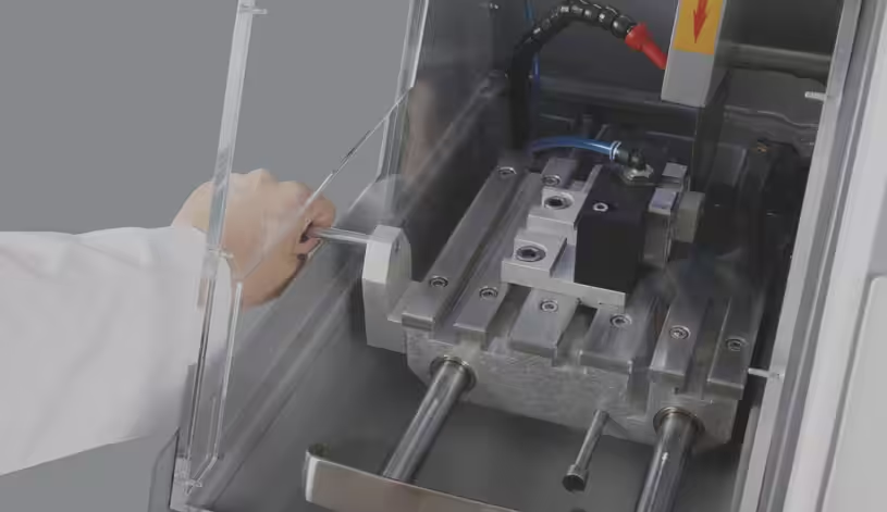
Thin sectioning machines
Specialized equipment makes all the difference in thin section preparation. Based on my experience, precision cutting machines like the Geocut and Geoform are specifically designed for geological applications, allowing for clean, accurate sectioning of rock samples. These machines use diamond-embedded cutting wheels to create smooth surfaces without fracturing delicate mineral structures.
Data from facts indicates that adequate thin sectioning requires:
- Diamond cut-offs (usually 200mm diameter, metal-bond
- Vacuum chuck systems utilized during glass slide cutting
- Diamond cup grinding wheels (175mm width, 65 micron) at initial thickness reduction
Later, vacuum systems are also instrumental during this process. The spec of equipment refers to vacuum pumps with a capacity of operating at heights of up to 2000m above sea level, plus fixed vacuum stands. These pieces of equipment keep rock samples absolutely stable during cutting procedures, with no slippage that may damage tender specimens or pose a hazard to safety.
Once the initial incision has been made, the specimen can be mounted. But before they are bonded together, the specimen and glass slide should first undergo a special treatment.
What is the Vickers Hardness Test? | Method, Applications & Advantages
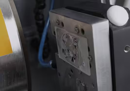
Bonding to glass slide using precision
Accuracy of the bonding process has a direct impact upon the quality of your finished thin section. First of all, both of your rock specimen and glass slide will both need roughening with 400 grit Silicon Carbide powder. Roughening produces microscopic textured surfaces which promote adhesion considerably.
All through the bonding process, one has to keep everything in perfect alignment. From the factual details, one stacks empty glass slides onto the sample holder with vacuum aid and achieves the right zeroing—a vital process ensuring an equal thickness of the complete sample.
Standard microscope slides (most are 27x46x1.27mm thick) are used as a base for thin sections. A thin volume of epoxy is used after positioning between the roughened material and microscope slide. The bonding epoxy used has a mix ratio similar to impregnation—5 parts resin with one part hardener.
Incidentally, the vacuum chuck systems mentioned in the equipment specifications are of different kinds for cutting and grinding glass slides of standard dimensions. These are special chucks with optimum positioning during preparation.
Drying and Curing Best Practices
Patience becomes a necessity during the curing process. As evident from the actual data records, the “sticking step” requires a full 8 hours of hardening. In the meantime, stable temperature conditions help prevent bubble evolution and encourage uniform curing of the bond.
Once the curing time has lapsed, subsequent operations are cutting and grinding. The prepared sample may first be trimmed off from excess material and then successively ground until the desired thickness has been attained. Here, the specimen changes from a rough cut specimen to a accurately mounted specimen suitable for the grinding stage.
While seeming simple, correct curing has a dramatic impact on the quality of your completed thin section. Hurrying through this process tends to cause:
- Premature separation during grinding
- Irregular thickness across the part
- Trapped air bubbles in the bond layer
The list of equipment also refers to special sample holders with boron carbide stops that are used to aid at sustaining uniform pressure and alignment at this critical phase. These components hold the sample firmly in position during the curing and subsequent grinding process.
By suitable cutting and mounting, we transform rough rock samples into properly positioned specimens firmly affixed to glass slides. This careful preparation opens the door to the next crucial step—grinding and thickness control—whose outcome will produce the usual 30µm thin sections desired for petrographic analysis.
Step 3: Grinding and Thickness Control
Once the specimen has been firmly attached onto the glass slide and sufficient curing time has elasped, grinding-an admittedly technically complex step of the process of thin-section preparation-is next. Here we are repeatedly reducing thickness to near-microscopic dimensions with a high order of accuracy.
Grinding with micrometer steps
Grind process involves a step-by-step progression from coarse to finer. Using the actual data, adopt a step approach for an optimum result:
- First pull off material in 50-micron steps until about a 200 micron thickness
- Once at 200 microns, bring step size back to 10-micron steps until you get to 100 microns
- Above 100 microns ,be quite careful, examining regularly under microscope
This graduated approach prevents accidental over-grinding, which would ruin hours of preparation work. The equipment specifications mention specialized tools like the GEOFORM 102 with vacuum chucks that maintain perfect positioning during this critical phase.
The wheel itself requires some specifications—most frequently a 175mm diamond cup grinding wheel with 65-micron diamonds. These types of high-accuracy tools create the completely flat surface required to obtain uniform thin sections.
30 µm or thinner thin-section thickness
The petrographic ideal of thin-section standards remains at 30 microns (0.030 mm), as at this precise thickness the great majority of minerals become transparent under reflected light while maintaining their characteristic optical characters.
Achievement of this preferred thickness needs technical skill and proper tools. First, dependent upon the auto grinding system until a depth of approximately 100 microns. then resort to manual techniques with 400 grit Silicon Carbide powder through the final reduction.
To achieve true thickness, calculate: Sample thickness = Total thickness – Glass thickness
Inspection with microscope for uniformity
At periodic intervals during the grinding course of action, quality checks through the microscope are of crucial importance. From the factual material, once the section has attained a thickness of 100 microns, checks become more frequent—every 2 minutes of grinding.
Under the microscope, You look for:
- Even thickness across the entire section
- Absence of scratches or grinding artifacts
- Consistent optical properties throughout the specimen
Some minerals have distinctive colors and interference patterns at particular thicknesses. Of all minerals, quartz makes a good thickness indicator because of stable optical properties. When well ground as a thickness of 30 microns, quartz generally produces first-order gray interference colors with crossed polarized light.
When grinding work is completed, the specimen goes through polishing—performed manually using special abrasives. As can be seen from the factual materials, finishing polishing parameters usually are as follows:
- Diamond abrasives (from 18μm to 6 μm)
- Water as lubricant
- Force of 15-20N per specimen
- Polishing times of 1-2 minutes per step
By meticulously paying attention to every micrometer of thickness, we convert pinned rock samples into clear windows into the mineral world. Laborious as this process may be, it becomes the precursor to all other petrographic analysis.
Step 4: Polishing and Coverslip Application
Polishing takes a rough-ground petrographic thin section and creates a clear glass-like window into the mineral world, disclosing details unseen at prior preparation steps. When the grinding has reached a desirable thickness, I proceed with the crucial polishing step—a process that will yield the ultimate quality and clearness of the petrographic thin-section.
Sequence of lapping and polishing description
The polishing process advances with a systematic sequence from coarse abrasives to finer abrasives. From the factual input, I carry out a multi-step treatment:
- Initial Grinding Step: Using 18μm diamond abrasive with water as lubricant, applied with 15N force for 1 minute at 150 rpm disk speed (clockwise rotation)
- Final Grinding: Switching over to 6μm diamond abrasive with water cooling lubricant, 15N load for 2 minutes at 120 rpm
- Polishing Step 1: Force of 20N at 2 minutes and 150 rpm (counter-clockwise direction)
- Polishing Finish: Applying and sustaining 20N force at 150 rpm (counter-clockwise) for 2 minutes
Meanwhile, the sample holder will rotate at 35 rpm clockwise and thus exhibit a counter-rotating action with the polishing disk. With this method, an equal abrasion occurs along the complete surface of the sample.
For manual polishing techniques, I also use a METAPO-B polishing surface (product code 39-033-300) with DIAPAT-M diamond abrasive (39-420-M) and with DIAPAT lubricant (39-502). Time consumed while using manual polishing is also approximately 8 minutes with a clockwise turning of 50 rpm.
Equipment specifications are the FORCIPOL TS with control unit that incorporates an aluminum disk (300mm) with splash guard. Others are special magnetic foil and sheet metal plates that retain polishing surfaces securely.
How to Prepare Metallographic Samples – Complete Step-by-Step Guide (With Expert Tips)
Preventing scratches and polishing faults
Small imperfections also skew the optical quality of sections. For the most part, flaws and scratches with:
- Washing samples gently between polishing steps to remove coarser abrasive particles
- Employing clean polishing compounds at each stage with no contaminated finer steps with rougher material
- Applying uniform pressure during the polishing action
- Providing proper lubrication at all times
For problem samples, frequent checks with the microscope allow you to spot possible problems before they become an issue. For example, once you’ve gotten up to a 100 micron thickness, you should check your samples with the microscope. If you’d like more grinding, I proceed with the 400 grit SiC Powder with 2-minute steps with checks during each step.
Clearly, rocks of differing kinds respond in a differing way while being polished. Empirical evidence indicates a successful preparation of three kinds of rocks—granite (55μm of ultimate thickness), peridotite (102μm), and tuffite (40μm)—which respond somewhat differently from one another due to their differing mineral assemblages and numbers of hardness.
Long-term storage with coverslip mounting
When the desired smoothness has been attained, an ultra-thin section has a coverslip applied and optical clearness improved. This last stage entails:
- Properly removing the surface that has undergone polishing of all polishing compounds
- Application of a razor-thin quantity of mounting medium onto the specimen
- Precautious covering of coverslip and preventing air bubble entrapment
- Leaving sufficient time suffices for solidification of mounting medium
The mounting medium’s refractive index must be chosen with specific consideration of petrographic analysis optical requirements. In addition to physical protection, coverslips also provide a flat smooth optical surface that increases the quality of images under both plane-polarized (PPL) and crossed-polarized (XPL) light.
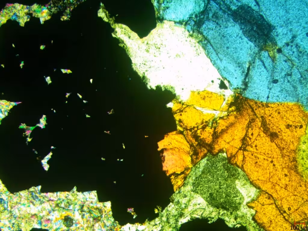
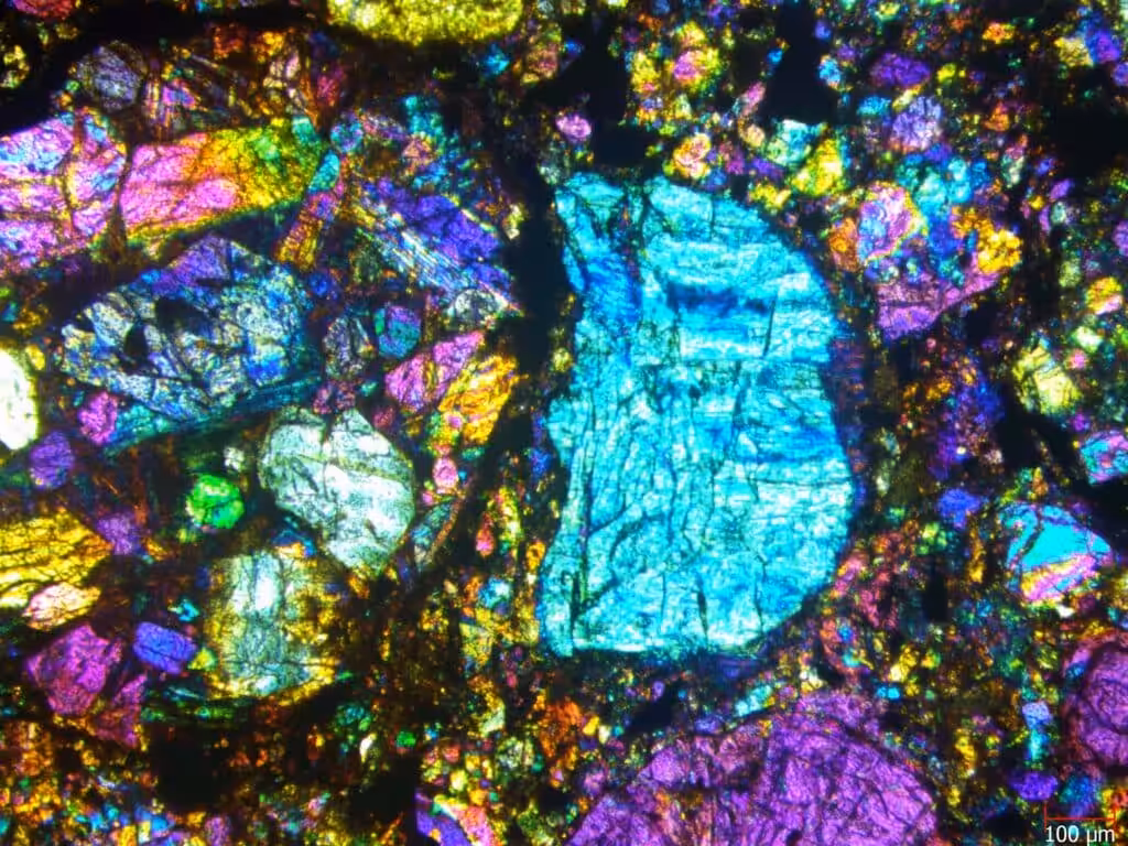
Under the polarizing microscope, thinly prepared sections display characteristic mineral structures. As we see from the factual records, “Different types of mineral structures are discernible. Micro observation carried out under the polarizing microscope.” Such microscopic observation is the culmination of the entire preparation process—where minerals are ultimately displaying their natural colors, their textures, and optical characters.
In the highest quality scientific applications, of course the ultimate thickness needs to be confirmed. The calculation is simplicity itself: Sample thickness = Total thickness – Glass thickness. In this neat little formula we can check if the desired 30μm thickness has been reached for best petrographic analysis.
Step 5: Final Analysis and Troubleshooting
The analytical stage is the reward of good prep work, as well-prepared sections at long last deliver their scientific value. Microscopic examination of material turns petrographic data of worth out of weeks of tedious prep.
Application of PPL and XPL while identifying minerals
The polarized light microscope has two main modes of examination that compliment each other for complete mineral identification:
Plane Polarized Light (PPL), with radiation oscillations confined between one plane only, illuminates the specimen and displays:
- Colour and pleochroism (change of colour as the stage revolves)
- Relief (visible height variations of minerals)
- Cleavage and fracture patterns
- Presence of inclusions or zoning
Cross Polarized Light (XPL) adds a second polarizer at right angles with the first one and unveils:
- Birefringence interference colors of minerals
- Angles of extinction when minerals are dark-colored
- Twinning associations typical of certain minerals
- Optical character (uniaxial or biaxial)
In essence, a specific method separates differing properties and identification of minerals becomes possible with systematic observation. The factual information offers an illustration of samples of granite, peridotite, and tuffite that are analyzed using polarizing microscope at differing magnifications (4x and 10x), describing how differing mineral structure becomes discernible through proper thin-section preparation.
Common problems: air bubbles, rim degradation, voids
Despite adequate preparation, a number of problems are frequent events with thin sections:
- Void and Crack formation: Most commonly a result of insufficient epoxy impregnation or ground-in stress, as with permeable materials such as tuffite.
- Air Bubbles: Most often developed during epoxy use or coverslip mounting, optical properties are distorted.
- Edge Loss: Edges are likely to crack or grow too narrow during grinding and lose informative boundaries.
- Uneven Thickness: Non-uniform grinding leads to inconsistent interference colors, making mineral identification challenging.
Suggestions towards improved edge retention and clarity
For optimum results with thin section analysis:
In short, check thickness frequently during grinding—the examples demonstrate successful one-step preparation of samples from 40-102μm (calculated from total thickness minus glass thickness).
Also observe samples with microscope every 2 minutes during final grinding steps, according to the actual data. Over-grinding while obtaining proper uniformity of thickness is thereby prevented.
Grind slowly near finish and with mild pressure only for edge retention. These vacuum chuck systems noted under equipment specifications assist retention of good positions while making preparations.
Finally, microscopic analysis is quality control and analysis—verifying uniform thickness while at the same time disclosing the characteristic mineral structures that render petrography an effective analytical method.
Conclusion
Thin-section preparation is an art and a science—all requiring accuracy, patience, and sophisticated equipment at every crucial stage. Demonstrably tedious work, it converts opaque rock material into clear windows through which the microscopic mineral world becomes available. In fact, proficiency in the five fundamental steps we detail—including careful sampling and impregnation and ultimate cutting and grinding and polishing and final analysis—invites single-minded practice yet produces irreplaceable geologic knowledge.
As part of our experience with this method, we’ve witnessed how vacuum impregnation hardens permeable samples so that they do not crumble during preparation. And good adhesion to glass slides develops a base for successful grinding through that crucial 30µm thickness at which minerals become clear while maintaining their characteristic optical properties. Most of all, careful polishing rough sections into transparent specimens suitable for close microscopic study.
The microscopic world unveiled with duly prepared thin sections enables geologists, materials scientists, and archaeologists to determine minerals, study microstructures, and make deductions regarding formation conditions otherwise irrecoverable. In addition, conformity with standards such as ASTM C856 and C295 enables uniformity of results from varying laboratories and applications.
Yes, pitfalls abound—air bubbles, uneven thickness, edge rounding—but with systematic procedures and regular quality control with the microscope, you can avert or obviate such challenges. Time-consuming as each process is, each one contributes to ultimate quality of your petrographic thin-section. Mastery of thin section preparation ultimately transforms your ability to conduct meaningful petrographic analysis. Therefore, whether studying ancient metamorphic rocks, analyzing concrete failures, or examining archeological artifacts, properly prepared thin sections provide the foundation for accurate scientific conclusions. This microscopic window into Earth’s materials reveals colors, textures, and mineral relationships that tell stories spanning billions of years—stories visible only through the transparent portal of a perfectly prepared thin section.
FAQs
Q1. What should the ideal thickness of a petrographic thin section be? The ideal thickness of a petrographic thin section should be around 30 micrometers (µm), roughly one-third of a human hair’s width. With such a thickness, the light can travel through the majority of minerals and still permit microscopic detail analysis.
Q2. Why is vacuum impregnation significant during thin section preparation? Vacuum impregnation becomes paramount particularly with rock samples that are porous or friable. Vacuum impregnation entails infilling pores with epoxy during vacuum conditions and it helps strengthen the rock and prevent it from disintegrating during cutting and grinding operations.
Q3. How are mineral IDs done from thin sections? Thin sections are examined with a polarizing microscope and with two chief methods: Plane Polarized Light (PPL) and Cross Polarized Light (XPL). PPL reveals features of relief and color and XPL reveals interference colors and extinction angles that aid in mineral ID.
Q4. What are common issues one encounters while making a thin section? Common issues while making a thin section are air bubbles, voids, edge loss and uneven thickness. These may be a result of insufficient epoxy impregnation, faulty mounting procedures or uneven polishing and grinding techniques.
Q5. What contributions has thin section analysis made to geology research? Thin section analysis contributes hugely to geology research by offering valuable information about the microscopic features of mineral composition, crystal structures and rock formation processes. Researchers are able to identify minerals, carry out a study of the microstructures and make geologic condition conclusions that cannot be made with other techniques.


