How to Prepare Metallographic Samples – Complete Step-by-Step Guide (With Expert Tips)
How to Prepare Metallographic Samples – Complete Step-by-Step Guide (With Expert Tips)
Correct materials analysis and characterization relies on correct metallographic sample preparation. Improper preparation can result in inaccurate results that misrepresent a material’s actual microstructure.
Certain materials pose special problems in preparation. As an example, magnesium alloys are difficult to prepare since their low matrix hardness and harder precipitate phases cause relief problems. Additional safety considerations are that fine Mg dust poses a serious fire risk.
There is a reason for each step in the metallographic process that leads to correct results. Proper sectioning is needed to minimize microstructural damage. High levels of lubricant with little abrasive are needed for soft materials to avoid damage from grinding and polishing.
This is a complete guide to metallographic sample preparation. You will learn all about documentation, cutting, mounting, grinding, polishing, etching, and microscopic examination with hardness testing. Tips from the experts will enable you to get the optimum results for your particular materials.
Automated Sample Preparation: Cut Operator Impact While Boosting Time & Cost Savings
Step 1: Document and Section the Sample
Your metallographic experience begins with sectioning and good documentation. These are the pillars of correct final analysis. Things being correct at the initial stage save you from mistakes that can destroy your entire investigation.
Why documentation matters in metallographic preparation
Record keeping is the foundation of metallographic analysis that allows you to reproduce and trace your results. Writing down detailed information on your preparation process is not paperwork – it is essential for scientific work. Your records must have equipment settings, consumables, and observations or difficulties you encounter during the process.
In addition to that, it renders metallography as an effective quality control and investigative technique. Proper documentation of the initial specimen condition and microstructural analysis provides you with a good baseline for future work. It comes in handy when you are comparing results with other laboratories, particularly with difficult or unusual samples.
Choosing the right cutting method for your material
Sectioning obtains a representative sample with the cross-section that you require. You will have to select a technique that preserves the actual microstructure of the material without introducing artifacts.
The following cutting methods are suitable for metallographic preparation:
- Wet abrasive cutting: The most widely used method produces little deformation (usually less than 200 μm from the cut surface). It employs special cut-off wheels with coolant to maintain low heat.
- Diamond wafer cutting: Most suitable for ceramics, electronics, biomaterials, and minerals.
- Band saws: Employed primarily for rough sectioning and seldom produce sufficient frictional heat to alter microstructure.
You should select the proper cut-off wheel according to material characteristics. The general rule states that soft-bonded wheels are best for harder materials, and hard-bonded wheels for softer materials. As an example, you can use a hard silicon carbide wheel on copper, but cubic boron nitride is most suitable for alloyed cast irons. Silicon carbide wheels (resin-bonded) tend to be good for quite ductile materials such as titanium or plastics.
What is Metallography? Definition, Techniques&; Industrial Applications
Tips to avoid microstructural damage during cutting
Improper cutting may destroy structure or alter material properties, which causes incorrect analysis results. Here is how to preserve the actual microstructure:
- Employ proper cooling – Insufficient cooling generates excessive heat that alters the microstructure of the material in an unpredictable manner. Ensure that you have proper cooling using the correct coolant.
- Add corrosion protection – Include a corrosion protection agent in your coolant to prevent surface oxidation on the cutting surface.
- Apply suitable cutting speed and pressure – Employ slow, steady feed rates to reduce deformation. When dealing with soft coatings that are less than 100 micrometers thick, ensure proper cutting speed to avoid burning.
4.\tConsider cutting modes for larger specimens – Larger components may require modes such as pulse cutting or planar cutting. Planar cutting makes shallow cuts in the specimen, which minimizes contact area to prolong wheel life and enhance cut quality.
- Inspect wheel condition – Most manufacturers print a manufacturing or best-before date on cutting wheels. The binders in the wheel absorb moisture over time, causing them to become brittle, wear more quickly, and be more prone to breakage.
Proper sectioning forms the basis of all subsequent metallographic preparation steps. When correctly done, it significantly minimizes the amount of material that you must remove by grinding and polishing. This not only saves time but also preserves your sample’s actual microstructural features.
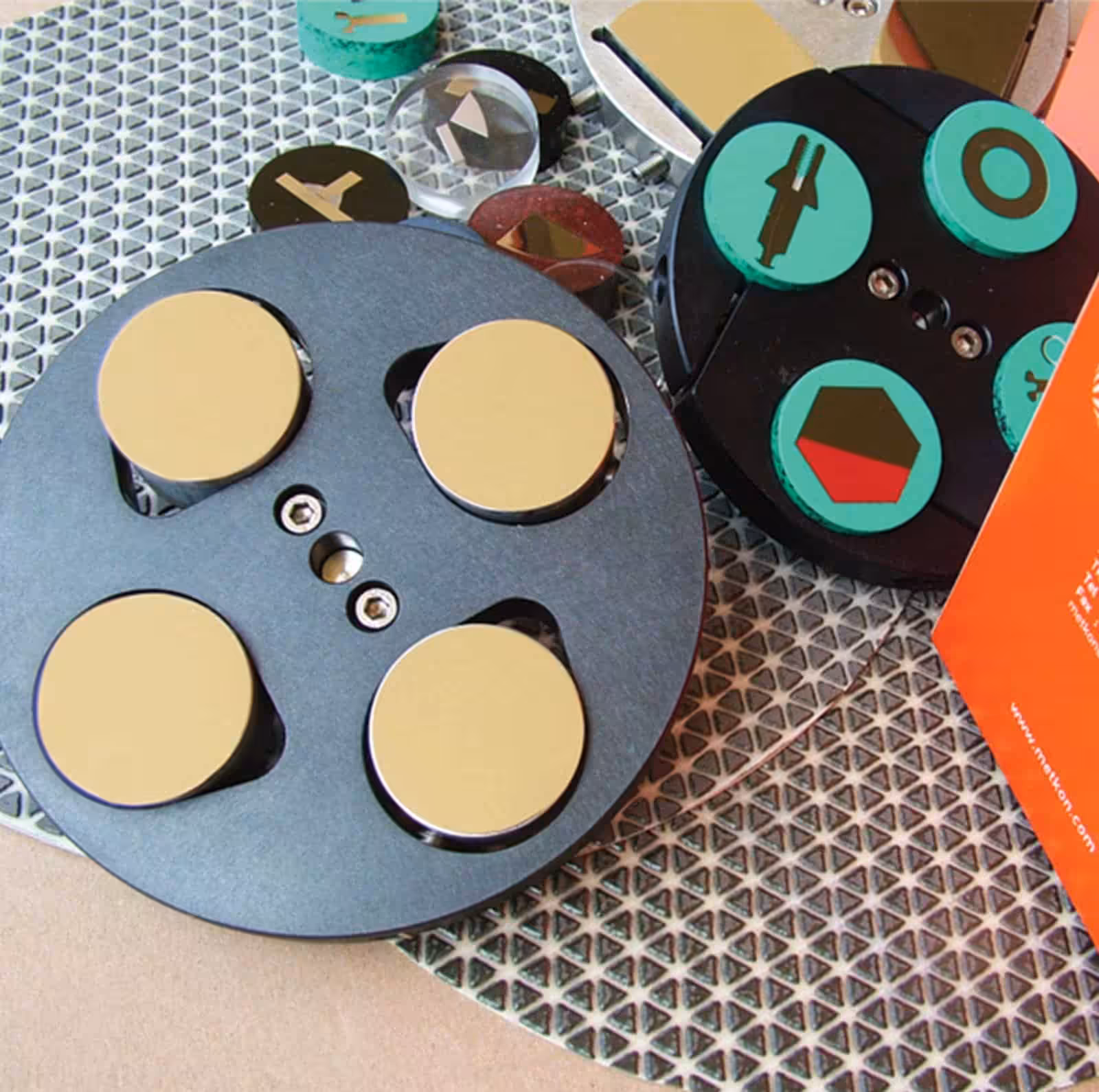
Step 2: Mounting the Specimen
Sample mounting is the crucial subsequent step in metallographic preparation following sectioning. The procedure safeguards your sample’s significant features and eases its handling by enclosing it in a proper medium.
When to use hot mounting vs. cold mounting
Hot mounting (compression mounting) places specimens in thermosetting resins or thermoplastics through the application of heat (150-200°C) and pressure (100-300 bar). This technique produces standardized mounts with edges intact, making it ideal for testing standard non-sensitive materials.
You’ll encounter these popular hot mounting materials:
- Phenolic resins (traditional, economical)
- Epoxy resins (improved edge retention)
- Diallyl phthalate (maintains edges)
- Conductive resins (for electron microscopy)
Cold mounting (castable mounting) involves liquid resins that cure without the application of external heat or excessive pressure. Don’t be misled by the name – polymerization can see temperatures up to 130°C. This technique is most suitable for:
- Heat or pressure-sensitive specimens
- Porous materials that require filling
- Oddly shaped samples
- Samples needing clear mounts
Best practices for edge retention and labeling
Maintaining your specimen’s edges intact is one of the greatest challenges of metallography. Here’s how you can preserve those edges flawless:
Hot mounting tips:
- Clean your specimens with acetone or alcohol
- Apply release agent to mounting press components to prevent resin from adhering
- Cool things down slowly to prevent stress and separation
- Avoid closed shapes or broad angles in specimens
- Try wrapping samples in aluminum foil
Cold mounting tips:
- Choose epoxy resins that flow well and shrink less compared to acrylics
- Use vacuum impregnation to achieve resin everywhere
- Make sure mounting material matches your specimen’s hardness
- Prevent sharp corners which form stress points
Identify your mounted specimens as soon as you make them. Hot mounts require details etched onto the back. You can place labels inside clear cold mounts or put markings on the outside using permanent markers.
Mounting porous or irregular samples
Porous materials require special care since air pockets will destroy your prep work and results. Vacuum impregnation alleviates these issues.
Here’s how to mount porous samples:
- Use epoxy resins that flow easily and are made for impregnation
- Obtain a vacuum chamber to extract air and allow resin to enter
- Mix dyes or fluorescent agents with epoxies to visualize the pores more easily
Cold mounting is better with irregular samples since it deals with odd shapes nicely. Rectangular cross-sections that are straightforward generally work either way.
Tips for complicated shapes:
- Make enclosing angles smaller to prevent resin shrinkage
- Rounded, convex edges hold up better than sharp or concave edges
- Add ceramic particles to match the resin’s hardness with your sample
Your mounting technique influences the quality of grinding and polishing later on. Properly mounted specimens are simpler to deal with and provide you with flatter surfaces, particularly with automatic equipment.
What is the Vickers Hardness Test? | Method, Applications & Advantages
Step 3: Grinding and Polishing Techniques
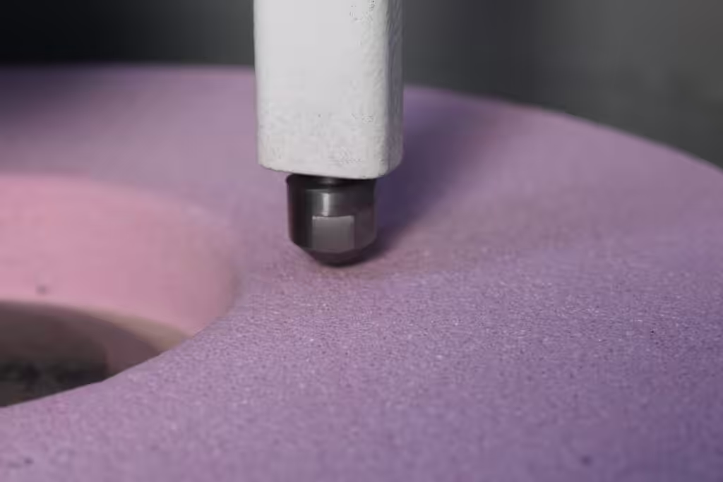
The grinding and polishing stage is the most time-consuming but is still very important in order to obtain reproducible metallographic results with your mounted sample. During this process, deformation is progressively removed and a surface is produced that reveals the actual microstructure.
Planar grinding: selecting abrasives and pressure
You require planar grinding for producing a flat surface and eliminating sectioning damage. Grinding Stones, Silicon carbide (SiC) papers or diamond grinding disks serve as good primary abrasives for most materials. Use coarser grits (80-120) to grind away heavy stock, followed by finer grades.
The quality of the grinding relies heavily on pressure control:
- Too much pressure creates unwanted artifacts and wears abrasives out rapidly
- Too little pressure is inefficient for material removal and produces uneven surfaces
The hardness of your material should direct abrasive selection—diamond abrasives are best for ceramics, carbides, and steels that have been hardened, with silicon carbide being more appropriate for softer metals. Moderate, consistent pressure grinds away material evenly and also makes grinding papers endure longer.
Automatic grinding polishing vs. manual methods
Automatic systems provide you with greater reproducibility and consistency—essential for quality control and verification. The machines can process several specimens simultaneously while accurately controlling force, direction, and speed settings.
Manual techniques allow you to work more flexibly with unusual or fragile specimens but rely on operator skill. Automatic polishing machinery produces flatter surfaces, preserves edges better, and allows you to save on consumables.
Automatic systems function optimally when you:
- Run at ~300 RPM for grinding and ~150 RPM for polishing
- Consider rotation direction—opposite directions remove material more quickly but cause greater deformation
Rough vs. final polishing: what’s the difference?
Rough polishing removes grinding deformation with diamond abrasives (commonly 9μm, 6μm or 3μm) on medium-hard cloths. It bridges grinding and final polishing and establishes the base for achieving quality results.
Final polishing creates a mirror-like, deformation-free surface with finer abrasives:
- Diamond (1μm or submicron)
- Aluminum oxide (0.3μm and 0.05μm)
- Colloidal silica (~10pH)
Alumina suspension produced by sol-gel yields improved surface finishes compared to conventional calcined alumina abrasives that are prone to agglomeration. Colloidal silica suspensions afford a combination of mechanical and chemical action, which is particularly beneficial for difficult-to-prepare materials.
Lubricants and polishing cloths: how to choose
Your preparation and material phase should dictate your choice of polishing cloth:
- Low-napped cloths (such as Metapo) are ideal for coarse polishing engineering materials
- Medium-napped cloths excel at intermediate polishing
- High-napped cloths (like Fedo) are ideal for final polishing of most metals
Lubricants must compromise between cooling and lubrication—soft materials require plenty of lubricant to avoid damage but less abrasive because they wear slowly. Hard materials require less lubricant but more abrasive as they wear quicker.
Your polishing cloths need to be damp but not wet for optimal performance. Excess lubricant removes abrasives from the disk and decelerates material removal. A cotton tuft dipped in detergent solution is suitable for manual operations, and automated systems must discontinue suspension addition 10-15 seconds prior to completion.
Step 4: Etching and Surface Enhancement
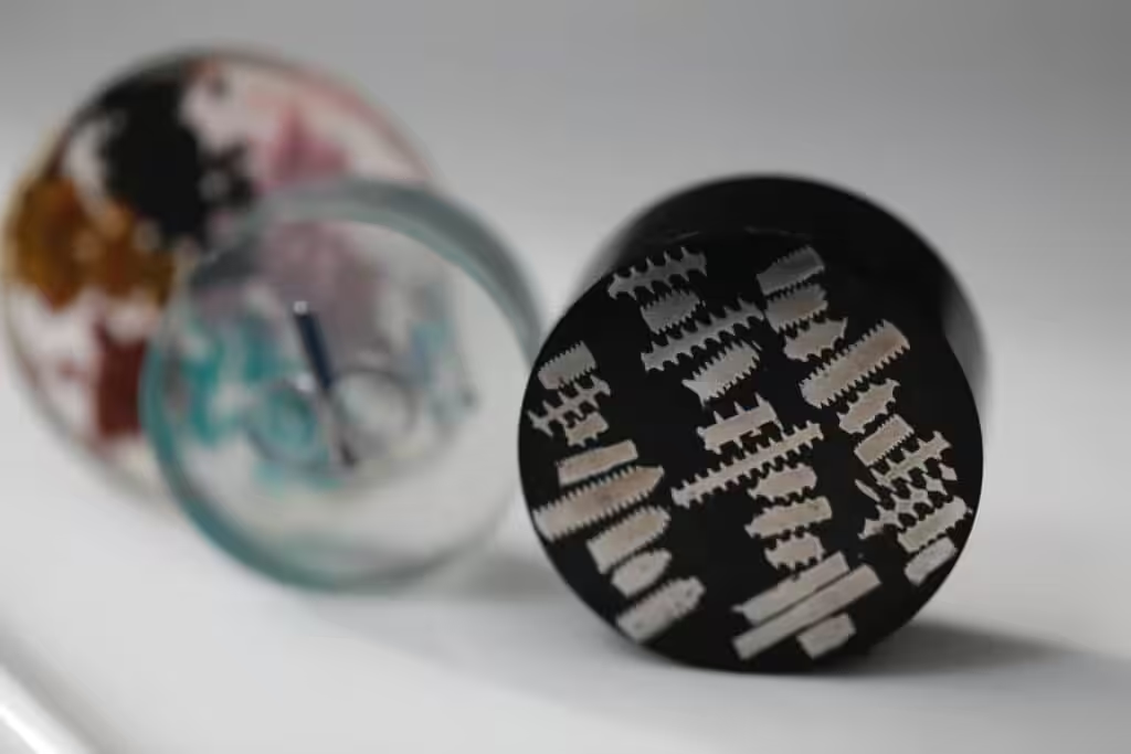
A mirror finish on your sample discloses the initial step. Etching is the next most crucial stage. It brings out concealed microstructural information that is not visible in the as-polished state.
Purpose of etching in metallographic analysis
Metallographic etching encompasses all those procedures that bring out structural features not apparent in the as-polished condition. The inspection prior to etching reveals porosity, cracks, and nonmetallic inclusions. Successful etching brings out grain size, segregation, and shape, size, and distribution of phases and inclusions in the material. Etching produces contrast among microstructural features by selective corrosion. This renders invisible features visible under microscopic inspection.
It’s notable that you ought to measure some constituents without etching. The procedure may bring out additional undesirable details that cause detection to be challenging or impossible.
Chemical vs. electrolytic etching methods
Chemical etching is the most widespread method in metallography. We employed this method due to its high cost-efficiency and simple usage. The process usually occurs by:
- Immersion – The surface of the sample is fully immersed in the etchant and swirled gently
- Swabbing – Soft tissues or cotton pads moistened with etchant are used to wipe the sample surface
Swabbing is particularly useful when you are dealing with metals that develop tenacious oxide surface layers such as stainless steels, aluminum, nickel, and titanium alloys. Etch time differs with etchant strength and experience will determine the best time.
Electrolytic etching requires an external voltage to be applied across the sample to drive the desired redox reaction. This method achieves greater removal rates even with its complexity. The outcome is totally deformation-free surfaces revealing the actual microstructure, something that’s far from achievable by other techniques.
Safety tips when handling etchants
Most etchants are very hazardous to health. Here is what you should do:
- Always wear proper eye protection, rubber gloves, and lab coats
- Mix and use etchants under sufficient ventilation (usually in a fume hood)
- Follow recommended first aid practices – wash skin with water for a minimum of 15 minutes in case of contact
- Store only regularly used reagents, and use dark-colored or cabinet-stored bottles
- Never keep nital (≥5% nitric acid in ethanol) in tightly sealed glass bottles since pressure generated by it can lead to explosions
- Use polyethylene containers for hydrofluoric acid (HF) etchants, since HF attacks glass
- Always add acids (especially sulfuric acid) slowly to water while stirring, never the reverse
Step 5: Microscopy and Hardness Testing
The final phase of metallographic sample preparation is the interpretation of the prepared specimen by using specialized microscopy and hardness testing procedures. These procedures reveal valuable microstructural details and mechanical properties that influence the performance of materials.
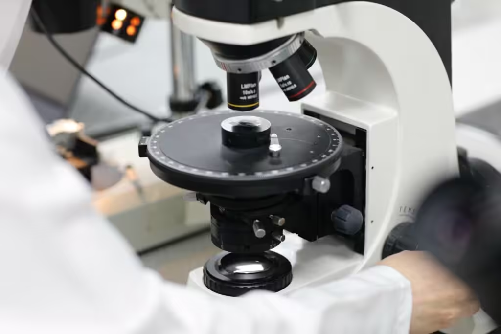
Microscopy techniques: bright field, dark field, DIC
Reflected light microscopy is the optimum instrument to examine opaque metallographic samples. Three methods cooperate to give total information:
Bright field (BF) illumination is the most typical method of examining metallographic specimens. Light travels from the source through the objective, reflects off the specimen surface, and returns through the objective to the eyepiece or camera. Flat surfaces appear bright, and non-flat features (pores, edges, etched grain boundaries) are darker since light reflects at angles.
Dark field (DF) illumination is a strong but less well-known method that directs light down the exterior of the objective. It produces a dark background for flat surfaces and non-flat features appear brighter. The method reveals grain structures that may remain invisible in bright field.
Differential Interference Contrast (DIC) enhances specimen details through the use of a Nomarski prism with crossed polarizers. Differences in height appear as differences in color, which creates a pseudo three-dimensional appearance for the specimen. DIC reveals surface defects that are not observed with other methods.
How to perform microhardness testing
Microhardness testing is an excellent method for obtaining mechanical property information of a material via small-scale indentation:
- Test selection: Choose either Vickers (square-based pyramid) or Knoop (rhombic-based pyramid) indenters depending on your material and test requirements.
- Preparation: The specimen must be well-prepared to obtain true hardness results.
- Testing procedure: Apply controlled force (10-1000 gram-force) for a fixed duration (typically 10-15 seconds) without impact.
- Measurement: Vickers requires both diagonal measurements; Knoop requires only the long diagonal.
- Calculation: Determine hardness by using formulas – HV = 1854.4L/d² for Vickers, HK = 14229L/d² for Knoop.
Using image analysis software for accurate results
Image analysis software has transformed microscopy from simple observation to quantitative evaluation:
The software assists in phase quantitation, inclusion counting, grain size, nodularity rating, porosity rating, and coating thickness. Programs such as Imagin Nodula combine microscopes, cameras, and analysis software via a simple interface.
Sophisticated systems automate hardness testing by quantifying Vickers, Knoop indents. These software packages produce comprehensive reports from analysis data, making documenting and communicating results fast and easy.
Conclusion
Developing proficiency in metallographic sample preparation undoubtedly requires attention to detail at each step. The procedure from initial documentation to final microscopy and hardness testing proceeds in a logical, building fashion. Each step exposes a material’s actual microstructure. Errors at any step can degrade your results significantly and lead to misinterpretation of essential material properties.
Good sectioning work lays the groundwork for successful analysis. Mounting safeguards fragile features and facilitates handling. Grinding and polishing operations eliminate deformation layers while the integrity of your sample remains intact. Etching subsequently exposes microstructural details that would otherwise remain invisible. Microscopy and hardness testing provide you with measurable information regarding the material’s properties.
Safety should remain your top concern during this process. This is particularly important when you work with dangerous chemicals in the course of etching. Material-specific considerations should influence your selection of methods, tools, and consumables at every preparation step.
Metallography is a combination of art and science – your proficiency will improve with practice over time. Frequent practice develops a feel for the optimum preparation parameters such as pressure, time, and abrasive choice. Keeping consistent records of your procedures builds up useful reference points which assist in future work and in troubleshooting.
This meticulous preparation method allows you to obtain consistent, repeatable results that reveal your material’s actual microstructure. The difference between poor and top-notch metallographic preparation frequently means the difference between critical, subtle material characteristics being revealed or remaining concealed from analysis.
FAQs
Q1. Why is proper documentation of metallographic sample preparation important? Proper documentation is important to guarantee reproducibility and traceability of results. It is a quality control measure and provides a good reference point for any future examination, particularly when working with non-standard samples or comparing results with other laboratories.
Q2. How do I decide whether to hot mount or cold mount my specimen? Hot mounting is the preferred method for routine examination of materials that are not sensitive, with very good edge retention. Cold mounting is preferred for heat- or pressure-sensitive specimens, porous samples, irregularly shaped samples, or when transparent mounts are required for visibility.
Q3. Compare rough polishing and final polishing in metallography. Rough polishing eliminates deformation due to grinding through the use of diamond abrasives (9μm, 6μm, or 3μm commonly) on medium-hard cloths. Final polishing produces a mirror-like surface free from deformation with the use of still finer abrasives such as submicron diamond, aluminum oxide, or colloidal silica.
Q4. Why is etching necessary in metallographic analysis? Etching develops microstructural information that cannot be seen in the as-polished condition. Etching produces contrast among microstructural components by selective corrosion, revealing such features as grain size, segregation, and shape, size, and distribution of phases and inclusions.
Q5. Which microscopy methods are commonly used in metallographic analysis? There are three major methods that are widely utilized: Bright field illumination, the most popular method; Dark field illumination, which clearly shows grain structures; and Differential Interference Contrast (DIC), which highlights surface details and gives a pseudo three-dimensional image of the sample.
")


